
System and method to fuse bone

Pending Publication Date: 2022-05-05
CRYOHEART LAB INC
View PDF0 Cites 0 Cited by
  • Summary
  • Abstract
  • Description
  • Claims
  • Application Information

AI Technical Summary

Benefits of technology

The patent describes an implant and method for stabilizing the sternal bones of a patient through the use of wires and a porous material that can hold cellular growth factors. The method also includes using a suction tube to create blood engorgement and harvesting patient materials like cancellous bone, cells, or blood. These materials can be added to a saline solution and used in the implant. The technical effect of this invention is to provide a stable and secure sternal construct that promotes bone growth and reduces pain for patients.

Problems solved by technology

Some parts of the body are not directly accessible via a simple incision and present additional challenges.
Unfortunately, patient recovery from a conventional sternotomy is often slow and problematic.
As the two sections (of the sternum) are brought back together by the surgeon, proper compression and a tight realignment of the end plates of the sternal surfaces is rarely achieved resulting in non-union, i.e. dehiscence, of separated sternal halves.
This non-union allows for motion such as sliding of the surface of one sternal half against the surface of the other sternal half leading to significant pain for the patient and increased chance for development of infection.
Additionally, the lack of proper compression leads to the formation of fibrous scar tissue instead of the desired new bone.

Method used


Image

  • System and method to fuse bone
  • System and method to fuse bone
  • System and method to fuse bone

Examples


Embodiment Construction

[0045]The following detailed description references the accompanying drawing that illustrates various embodiments of the present inventive concept. The illustration and description are intended to describe aspects and embodiments of the present inventive concept in sufficient detail to enable those skilled in the art to practice the present inventive concept. Other components can be utilized and changes can be made without deviating from the scope of the present inventive concept. The following detailed description is, therefore, not to be taken in a limiting sense. The scope of the present inventive concept is defined only by the appended claims, along with the full scope of equivalents to which such claims are entitled.

I. Terminology

[0046]The phraseology and terminology employed herein are for the purpose of description and should not be regarded as limiting. For example, the use of a singular term, such as, “a” is not intended as limiting of the number of items. Also, the use of ...


PUM

PropertyMeasurementUnit
Structureaaaaaaaaaa
Stabilityaaaaaaaaaa

Abstract

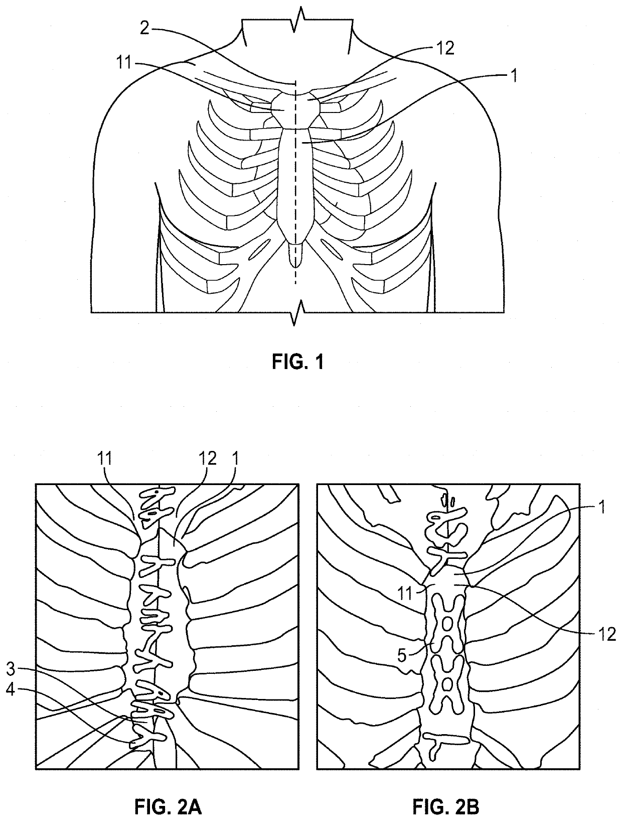
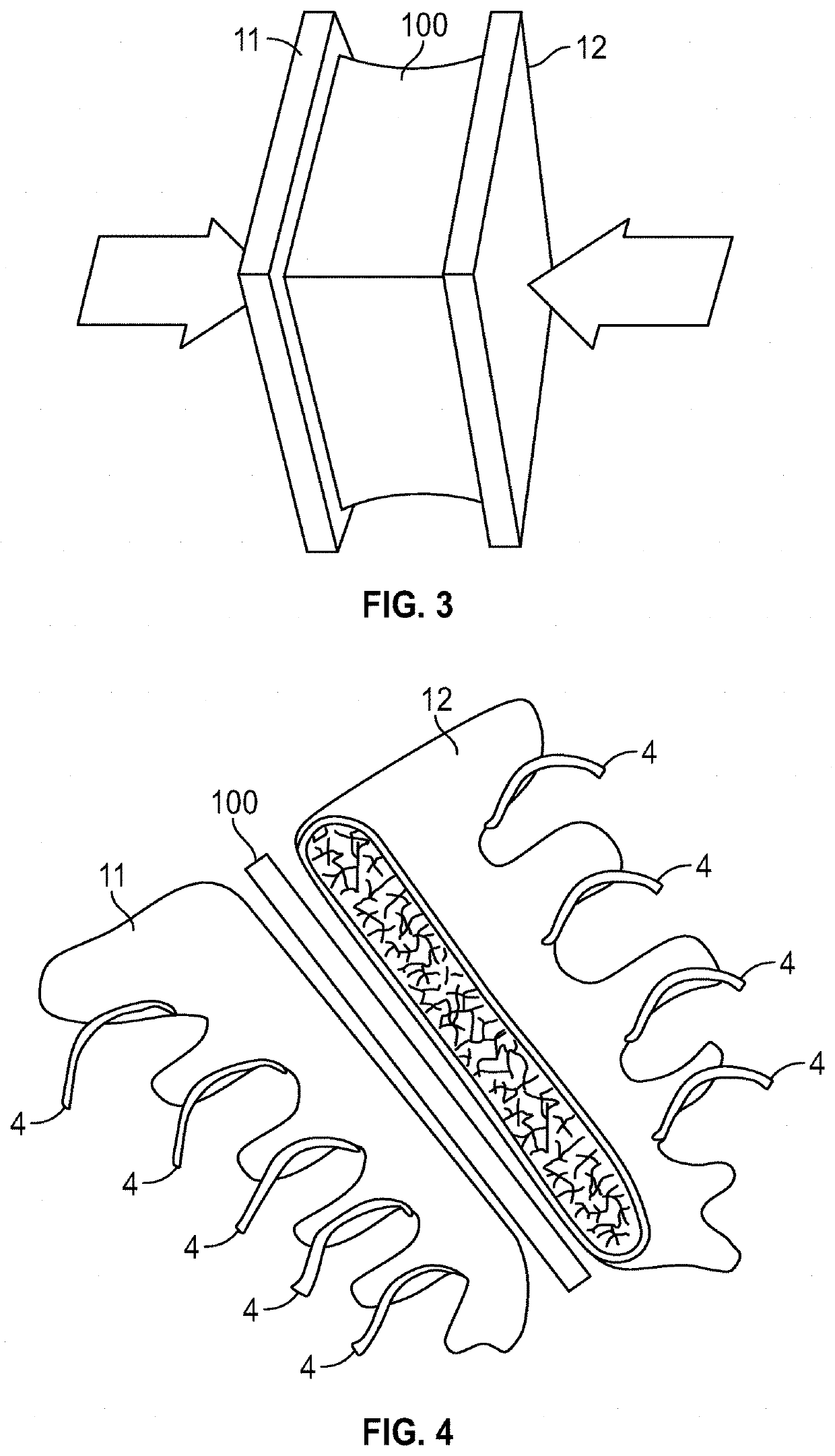
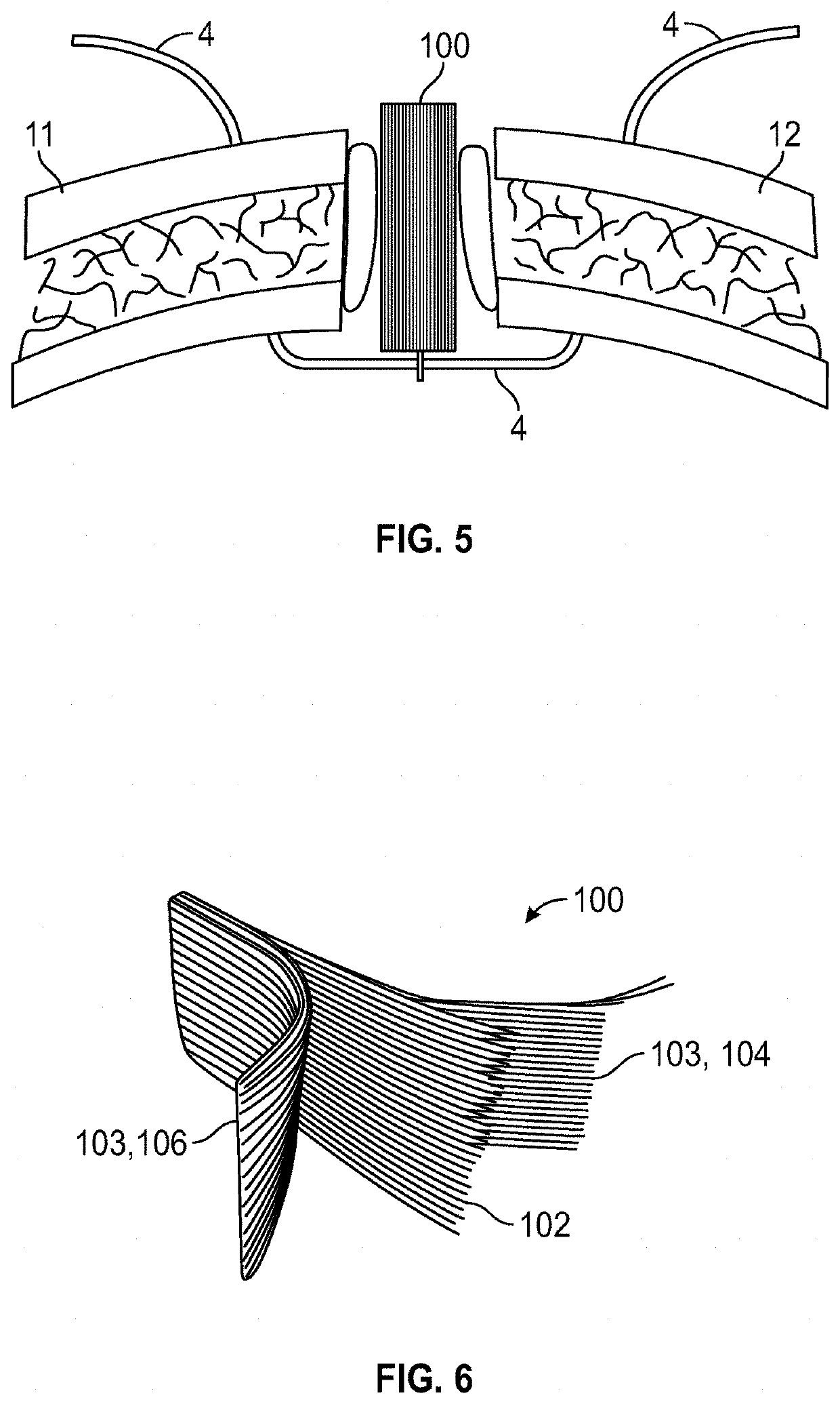
Systems and methods include a method to fuse two sections of bone. The method includes various operations such as accessing the chest cavity (e.g., by severing the sternum) and preparing the sternal edges of the two sections of bone. Sternal wires are implanted around the two sections of bone to create a cradle in a space between the two sections of bone. Cancellous bone tissue may be harvested from the patient and used to hydrate an implant before trimming the implant and / or placing the implant in the cradle. The sternal wires are tightened to compress the implant between the two sections of bone; and the ends of the sternal wires are tied together to create a sternal structure comprised of the implant tightly compressed between the two sections of bone. The sternal construct can act as a bone gasket to improve healing and fusing for the two sections of bone.

Description

CROSS-REFERENCE TO RELATED APPLICATIONS[0001]This application is a continuation-in-part of U.S. application Ser. No. 16 / 669,857 filed in the U.S. Patent and Trademark Office on Oct. 31, 2019, which claims the benefit of U.S. application Ser. No. 16 / 517,276, filed in the U.S. Patent and Trademark Office on Jul. 19, 2019, which claims the benefit of U.S. Provisional Patent Application No. 62 / 700,378, filed in the U.S. Patent and Trademark Office on Jul. 19, 2018, each of which is incorporated herein by reference in its entirety for all purposes.BACKGROUND1. Field of the Invention[0002]The present inventive concept relates to systems and methods to heal and / or replace bone. In at least one example, the present inventive concept relates to an implant system and method to stabilize and fuse two halves of a sternum in a patient post-sternotomy.2. Description of Related Art[0003]Physical intervention in tissue of a human or an animal, for example surgery, dates to prehistoric times. During...

Claims


Application Information

Patent Timeline
IPC IPC(8): A61F2/28A61F2/30
CPCA61F2/28A61F2310/00017A61F2/30749A61F2310/00023A61F2002/30784A61F2002/30677A61F2002/3093A61F2002/30884A61F2002/2817A61F2002/30891A61F2002/30576A61F2310/00359A61F2310/00371A61F2002/3092A61F2/30771
Inventor THABET, II, FREDERICK J.KANAGALA, RAVISEARLE, JAMES
Owner CRYOHEART LAB INC
Learn More