Method for determining a switching point of a solenoid valve

a solenoid valve and switching point technology, applied in the direction of electric control, magnetic bodies, machines/engines, etc., can solve the problems of incorrect identification, poor quality of the signal ultimately to be evaluated, and inability to permit inferences, so as to improve the quality of the underlying signal, improve the signal profile, and improve the effect of accuracy

Pending Publication Date: 2022-04-28
ROBERT BOSCH GMBH
View PDF0 Cites 0 Cited by
  • Summary
  • Abstract
  • Description
  • Claims
  • Application Information

AI Technical Summary

Benefits of technology

The invention provides a method for controlling the timing of signals in a system using a solenoid valve. The method allows for easy adjustment of the temporal length of periods to ensure that the fastest increase in the signal profile is adequately covered. The method can be implemented as a computer program or computer program product, which is cost-effective and adaptable to different cases. The technical effect of the invention is that it simplifies the process of controlling the timing of signals in a system and makes it easier to adapt to different requirements.

Problems solved by technology

The knowledge of the activation points in time, which indicate the application or removal of a voltage to or from the solenoid coil, generally does not permit inferences about the point in time at which the flow opening is actually unblocked—the switching point.
However, since upon the differentiation of a signal such as that of the current profile interferences in the signal or interferences which overlay the actual signal are also differentiated, this may result in a poor quality of the signal ultimately to be evaluated and thus in incorrect identifications.
This makes the application to the specific case difficult.

Method used


Image

  • Method for determining a switching point of a solenoid valve
  • Method for determining a switching point of a solenoid valve
  • Method for determining a switching point of a solenoid valve

Examples


Embodiment Construction

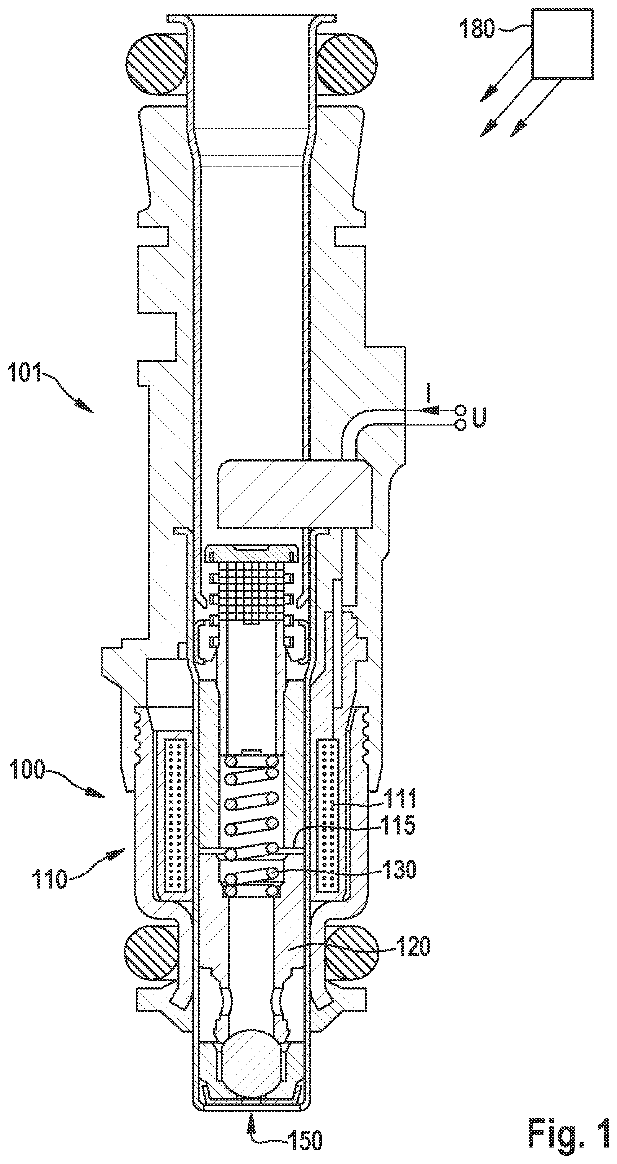
[0021]FIG. 1 schematically shows a solenoid valve 100, which is used, for example, in a fuel injector 101 and in which a method according to the present invention may be carried out. Solenoid valve 100 includes an electromagnet 110 including a solenoid coil 111, which may be designed to be annular, for example. Upon application of a voltage U, for example, by an executing processing unit 180 designed as a control unit, current I flows in solenoid coil 111.

[0022]Furthermore, a solenoid armature 120 is provided, which is moreover used as a valve needle, using which a flow opening 150 may be closed or unblocked. Furthermore, a spring 130 is provided, which engages on solenoid armature 120 and, without energization of solenoid coil 111 and thus without magnetic force, presses armature 120 into or against flow opening 150 and closes it. Spring 130 may be in contact on its side facing away from the solenoid armature at a suitable component of solenoid valve 100.

[0023]Upon energization of ...


PUM


Abstract

A method for determining a switching point of a solenoid valve. A solenoid coil is energized to raise a solenoid armature to unblock a flow opening. For a signal profile characteristic of a current profile in the solenoid coil, multiple periods each different from one another and each having the same predefined temporal length are determined. Within each period, a minimal and a maximal value of the signal profile and associated points in time are ascertained and a product of a difference between the maximal and minimal value and a difference between the associated points in time are ascertained. On the basis of the points in time of the minimal and maximal value of that period, which corresponds to a maximal value of the product, the switching point is determined.

Description

FIELD[0001]The present invention relates to a method for determining a switching point of a solenoid valve and a processing unit and a computer program for carrying out the method.BACKGROUND INFORMATION[0002]Solenoid valves include a solenoid coil and a solenoid armature, which is raised or lifted by energizing the coil—a certain voltage is typically applied for this purpose—and a flow opening is thus unblocked. A typical use of solenoid valves is in fuel injectors. The solenoid valve may typically be used there to unblock or close a flow opening for fuel.SUMMARY[0003]According to the present invention, a method for determining a switching point of a solenoid valve as well as a processing unit and a computer program for carrying out the method are provided. Advantageous embodiments of the present invention are described herein.[0004]The present invention relates to determining a switching point of a solenoid valve, as was already explained at the outset. The knowledge of the activat...

Claims


Application Information

Patent Timeline
Patent Type & Authority Applications(United States)
IPC IPC(8): F16K37/00
CPCF16K37/0041F16K31/06F02D41/20F02D41/3005F02D2041/2055F02M51/061H01F7/1844F02D2041/2058
Inventor RUPP, ANDREASREINEKE, BASTIANHERRMANN, PAUL
Owner ROBERT BOSCH GMBH
Why Eureka
Try Eureka