
Scrap cutter

a cutter and scraper technology, applied in the field of scrapers, can solve the problems of left-right vibration generation, machine is not suitable for high-speed operation, and the shear angle is gradually reduced, and achieves the effects of high efficiency, high speed, and formed shear angl

Pending Publication Date: 2022-04-28
AIDA ENG LTD
View PDF13 Cites 0 Cited by
  • Summary
  • Abstract
  • Description
  • Claims
  • Application Information

AI Technical Summary

Benefits of technology

The present invention is related to a scrap cutter that can efficiently and quickly cut scrap materials fed from a press machine. The cutter has a unique cutting mechanism that reduces the shear angle of the moving blade, which improves the cut surface quality and reduces breakage of the cut section. By optimizing the shear angle, the cutter can achieve high efficiency and speed in scrap cutting.

Problems solved by technology

However, because the blade holder including the moving blade swings, left-right vibration is generated and the machine is not suitable for high speed operation.
However, the reason why the shear angle is gradually reduced is not in consideration of the press capacity at the time of cutting.

Method used


Image

  • Scrap cutter
  • Scrap cutter
  • Scrap cutter

Examples


Embodiment Construction

[0039]Preferred embodiments of scrap cutters according to the present invention is to be described below in detail with reference to the accompanying drawings.

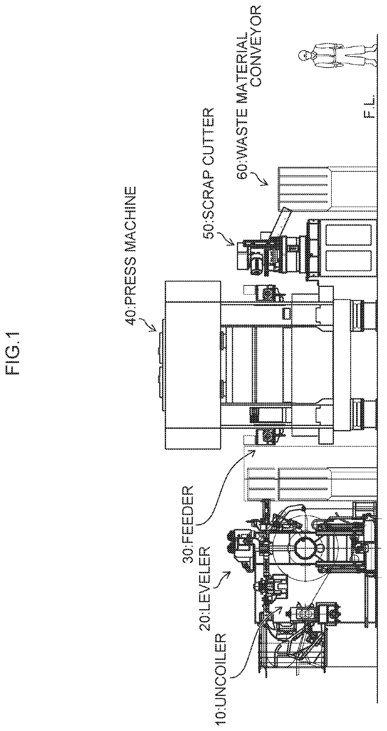
[0040]FIG. 1 is a layout diagram of a press line including a scrap cutter according to the present invention.

[0041]The press line shown in FIG. 1 includes an uncoiler 10, a leveler 20, a feeder 30, a press machine 40, a scrap cutter 50 and a waste material conveyor 60, which are sequentially arranged in this order.

[0042]The uncoiler 10 is a material supply apparatus that unwinds a material wound around a drum in a coil shape (coil material) and supplies the unwound coil material while controlling the bending of the coil material.

[0043]The leveler 20 is arranged between the uncoiler 10 and the feeder 30. The leveler 20 holds (sandwiches) the coil material between a plurality of alternately arranged rolls, and alternately deforms the coil material in the vertical direction to remove the strain from the coil material having curl....


PUM

PropertyMeasurementUnit
shear angleaaaaaaaaaa
thicknessaaaaaaaaaa

Abstract

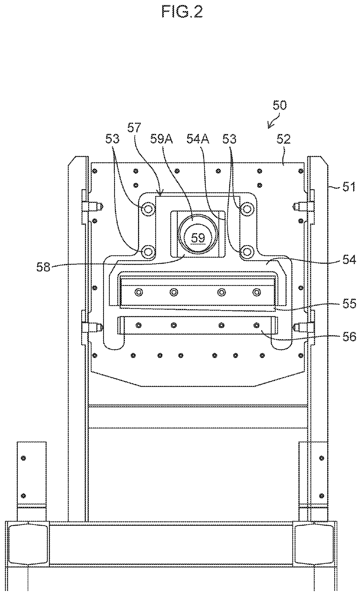
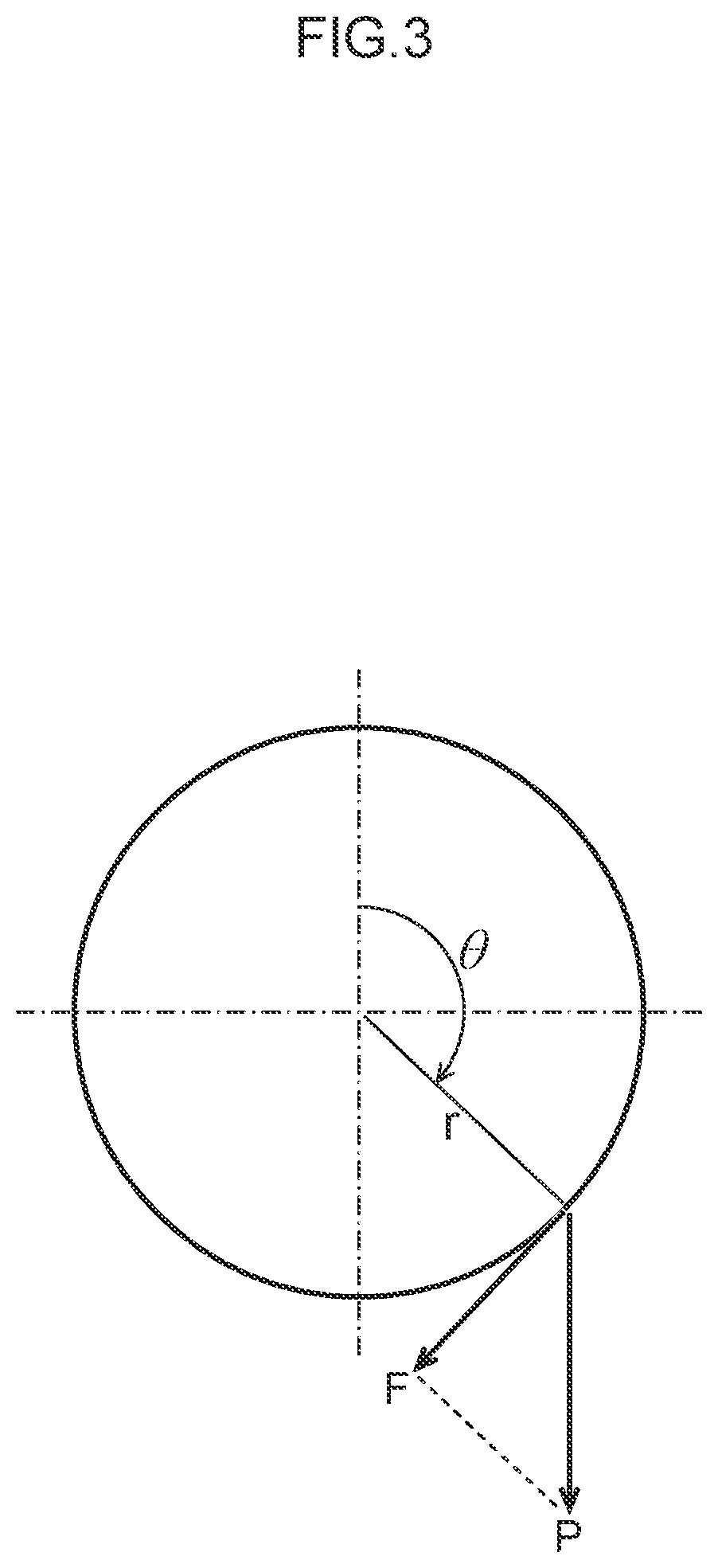
A scrap cutter is provided in a subsequent stage of the press machine and cuts the scrap material fed from the press machine. The scrap cutter includes: a slide configured to be driven to reciprocate in the vertical direction by a Scotch yoke mechanism; an upper blade attached to the slide; and a lower blade attached to a frame and configured to cut the scrap material in cooperation with the upper blade. A shear angle formed by the upper blade and the lower blade has an angle that gradually decreases from a start of cutting of the scrap material toward an end of cutting to allow the driving torque of the crankshaft of the Scotch yoke mechanism to be constant from the start of cutting to the end of cutting in cutting a scrap material of a cutting capacity limit.

Description

CROSS-REFERENCE TO RELATED APPLICATIONS[0001]The present application claims priority under 35 U.S.C. § 119 to Japanese Patent Application No. 2020-177866 filed on Oct. 23, 2020. The above application is hereby expressly incorporated by reference, in its entirety, into the present application.BACKGROUND OF THE INVENTIONField of the Invention[0002]The present invention relates to a scrap cutter, and more particularly to a scrap cutter capable of cutting scrap material fed from a press machine with high efficiency and high speed.Description of the Related Art[0003]The types of scrap cutters include: a scrap cutter which cuts scrap materials between a fixed blade and a moving blade (cutter blade) which is reciprocated in the vertical direction by a crank mechanism or the like; and a scrap cutter having a structure in which a cutter blade is directly attached to a lower end of a connecting rod connected to a crankshaft and is pin-guided in the vertical direction toward the vicinity of th...

Claims


Application Information

Patent Timeline
Patent Type & Authority Applications(United States)
IPC IPC(8): B23D15/12B23D15/04
CPCB23D15/12B23D15/04B21D43/28B23P23/04B23D15/08B23D35/001B23D31/008
Inventor ITO, TAKAO
Owner AIDA ENG LTD
Learn More