Esophageal ablation technology
a technology of esophageal ablation and ablation chamber, which is applied in the field of thermal ablation devices and devices, can solve the problems of increasing the risk of developing esophageal cancer, significant limitations and shortcomings of existing technology in this field, and achieves the effect of safe and effective treatmen
- Summary
- Abstract
- Description
- Claims
- Application Information
AI Technical Summary
Benefits of technology
Problems solved by technology
Method used
Image

Examples
first embodiment
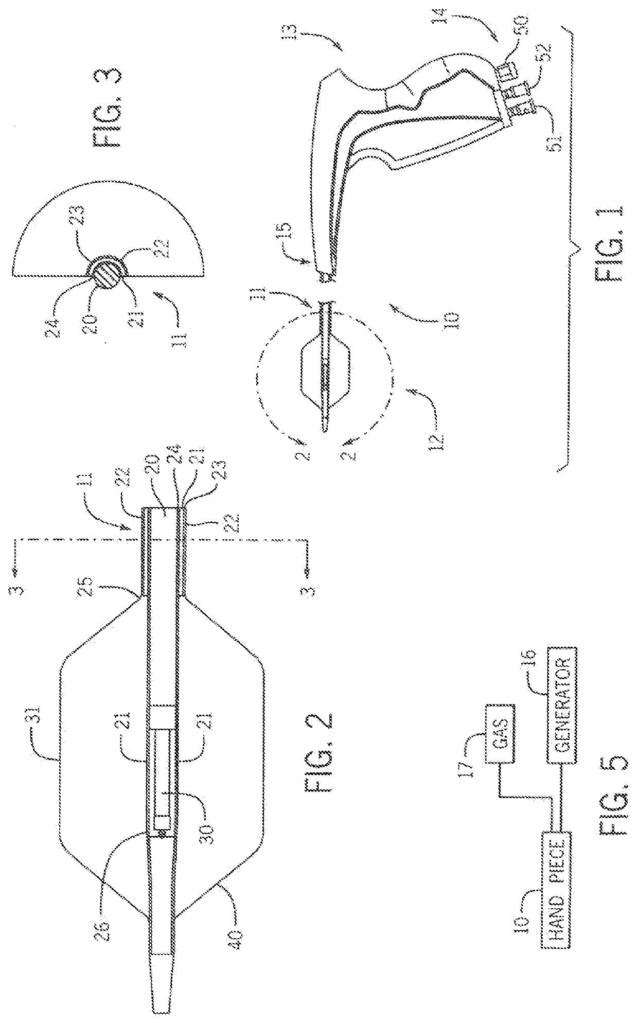
[0075]FIGS. 1-3 show the esophageal ablation system of the present invention. The system 10 comprises a handset including an elongated, flexible shaft 11 and an emitter assembly 12 at the terminal, distal end of the shaft 11. The system preferably includes a hand piece type positioner 13 which is manipulated by a user to insert and steer the shaft 11 and emitter assembly 12 into and through the mouth and esophagus of a patient. The hand piece 13 has a connection end 14 for communicative mating with fluid systems and power systems. The hand piece 13 also has a distal end 15 from which the shaft 11 extends.
[0076]Referring also to FIGS. 2 and 3, the elongated, flexible shaft 11 comprises a central power cable 20, which is preferably coaxially surrounded by an inner layer 21 and an outer layer 22. The power cable 20 conducts microwave power from a power generator (shown in FIG. 5 and discussed below) to the emitter assembly 12. An outer lumen 23 is formed between the outer layer 22 and ...
second embodiment
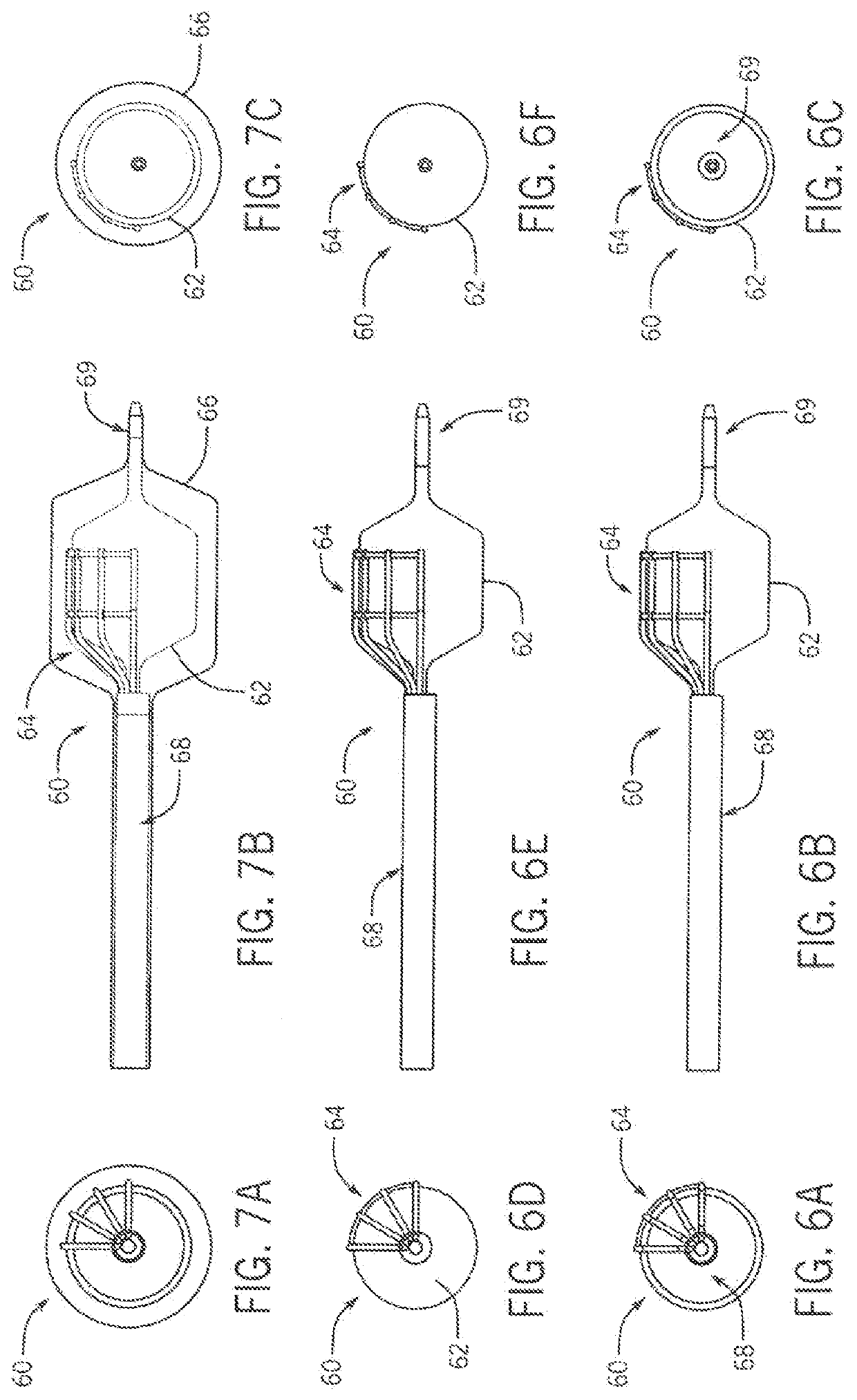
[0083]FIGS. 6 and 7 show the device 60 of the invention with a compliant inner deployment balloon 62, an antenna array 64 mounted there over and with fixed angular spacing, and a compliant outer positioning balloon 66. The device 60 also has a proximal shaft assembly 68 and a distal tip assembly 69. The inner balloon 62 diameter may is controllable to fix or optimize the distance between the antenna 64 and the ablation target. The antenna array is rotatable from the handle to enable circumferential ablation. The antenna 64 struts constrain the arc length between adjacent antennas. This maintains the distance between antennas thereby fixing the amount of overlap between electric fields. The overlap is constant over a full diameter range.
[0084]Alternatively, the antennas may also be constructed and arranged in a linear array to cover a greater axial distance. Lastly, it is within the purview of the invention that the device 60 could be constructed of a self expanding scaffold antenna ...
fourth embodiment
[0087]Referring to FIGS. 11-14, the device 100 comprising a balloon 112 attached proximally to an outer shaft 114 and distally to a tip 116 with a thru lumen 118. The balloon 112 is preferably constructed of urethane. The balloon 112 is shown in an expanded state. It can expand to accommodate the full range of esophagi lumen diameters. The urethane balloon 112 is preferably inflated with air. The function of the urethane balloon 112 and outer shaft 114 is to create a deterministic circular lumen of known diameter inside the esophagus of a patient. The outer shaft 114 is connected to a handle and allows for the insertion of the entire assembly 110 down the mouth of the patient to the target in the esophagus. Exemplary handles embodiments are shown in FIGS. 1, 25 and 28.
[0088]As is best shown in FIGS. 12-14, inside the balloon 112 and outer shaft 114 is an inner shaft 120. The inner shaft 120 contains a coaxial cable 122 and a pull wire 124. The coaxial cable 122 connects to an antenn...
PUM
 Abstract
Description
Claims
Application Information
 - R&D
- Intellectual Property
- Life Sciences
- Materials
- Tech Scout
- Unparalleled Data Quality
- Higher Quality Content
- 60% Fewer Hallucinations
Browse by: Latest US Patents, China's latest patents, Technical Efficacy Thesaurus, Application Domain, Technology Topic, Popular Technical Reports.
© 2025 PatSnap. All rights reserved.Legal|Privacy policy|Modern Slavery Act Transparency Statement|Sitemap|About US| Contact US: help@patsnap.com