Motor drive control device and motor drive control method

a control device and motor technology, applied in the direction of electric generator control, dynamo-electric converter control, dynamo-electric gear control, etc., can solve the problems of not being able to accurately not being able to estimate the rotation position of the rotor, and not being able to reduce the arithmetic load of sensorless vector control. , to achieve the effect of reducing the arithmetic load

Active Publication Date: 2022-04-21
MINEBEAMITSUMI INC
View PDF2 Cites 2 Cited by
  • Summary
  • Abstract
  • Description
  • Claims
  • Application Information

AI Technical Summary

Benefits of technology

The patent aims to reduce the arithmetic load in sensorless vector control. In simple terms, this means that the invention proposes a way to decrease the calculations needed for controlling the movement of a robot arm or other systems without using sensors.

Problems solved by technology

However, in the method for estimating the rotation position of the rotor by utilizing the induced voltage generated in the coil of the motor, the induced voltage depends on the rotation speed of the rotor, and thus, it is not possible to estimate the rotation position of the rotor when the rotor is stopped.
Additionally, when the rotor rotates at a relatively low speed, the rotation position of the rotor cannot be estimated accurately.
Furthermore, in the method for estimating the rotation position of the rotor on the basis of the saliency of the motor, in the case of a motor having no saliencies and identical d-axis inductance Ld and q-axis inductance Lq (Ld=Lq) as in the surface permanent magnet synchronous motor (SPMSM), it is not possible to estimate the rotation position of the rotor.

Method used


Image

  • Motor drive control device and motor drive control method
  • Motor drive control device and motor drive control method
  • Motor drive control device and motor drive control method

Examples


embodiment

Expansion of Embodiment

[0142]The invention contrived by the present inventors has been described in detail above with reference to the embodiment. However, the present invention is not limited to the embodiment, and various modifications can be made without departing from the gist of the present invention.

[0143]For example, in the above embodiment, a case where the drive command signal Sc is the speed command signal Sc1 including a target value of the rotation speed (target rotation speed) of the motor 3 is described in an example, but the embodiment is not limited to this case. For example, the drive command signal Sc may be a torque command signal Sc2 for specifying torque of the motor 3. Below, another example of a control circuit in a case of the torque command signal Sc2 as the drive command signal Sc being input to a motor drive control device will be described.

[0144]FIG. 6 is a diagram illustrating a functional block configuration of a control circuit in a motor drive control...


PUM


Abstract

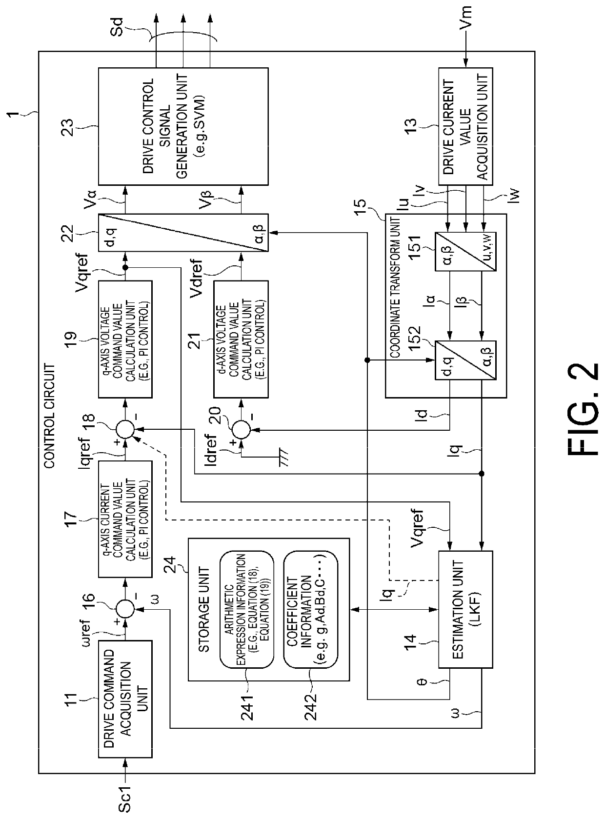
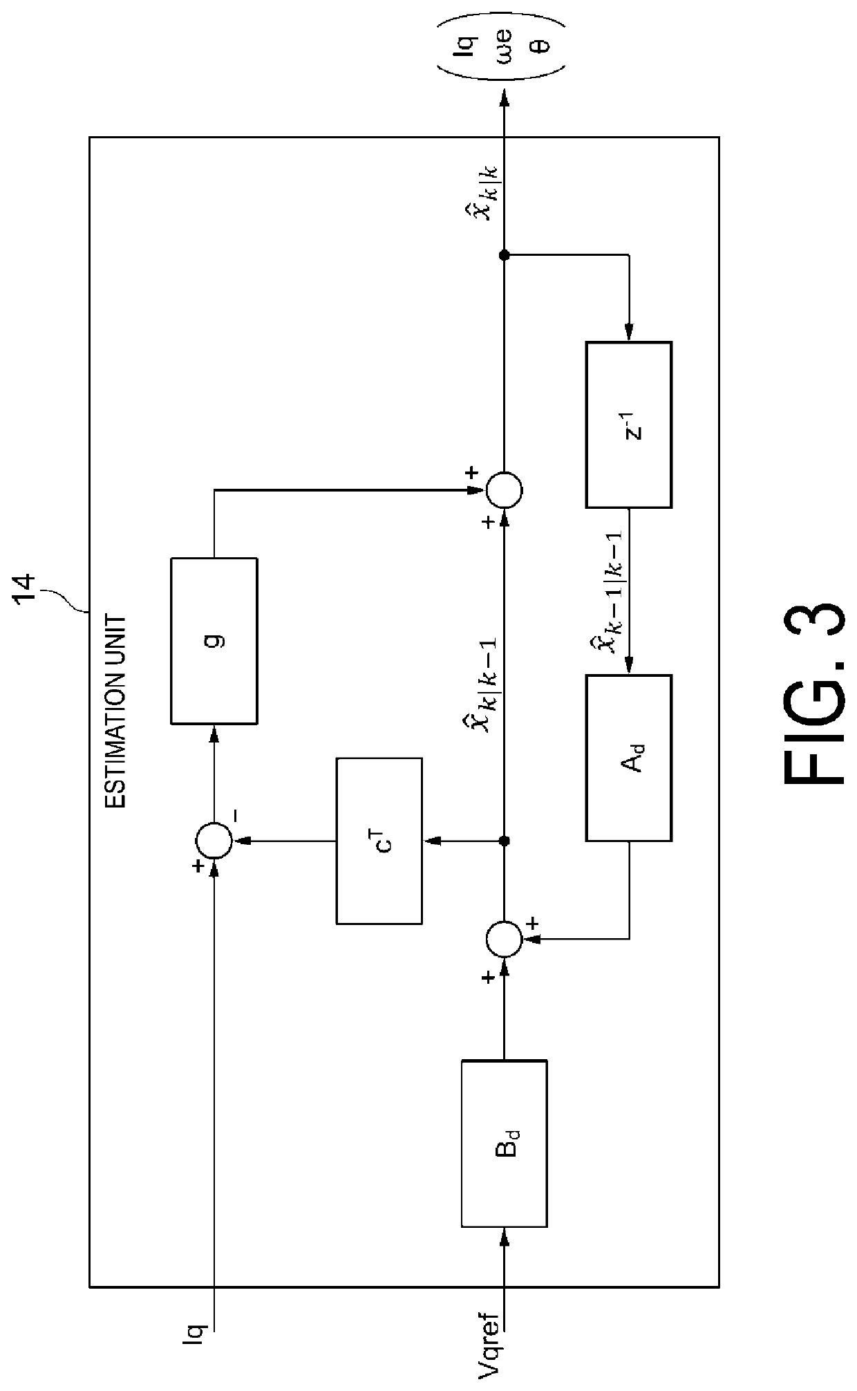
A motor drive control device includes a drive circuit configured to drive a motor with a drive control signal for driving the motor, and a control circuit configured to perform a vector control arithmetic operation based on a detection result of drive currents of coils of the motor, to generate the drive control signal and supply the drive control signal to the drive circuit. When generating the drive control signal, the control circuit estimates a rotation angle of a rotor of the motor and a rotation speed of the rotor with a q-axis current value of a two-phase rotating coordinate system calculated with a detection result of the drive current, and a q-axis voltage command value of the two-phase rotating coordinate system, by using a linear Kalman filter including a prediction step and an update step, using a stationary Kalman filter with the prediction step expressed linearly and time-invariantly.

Description

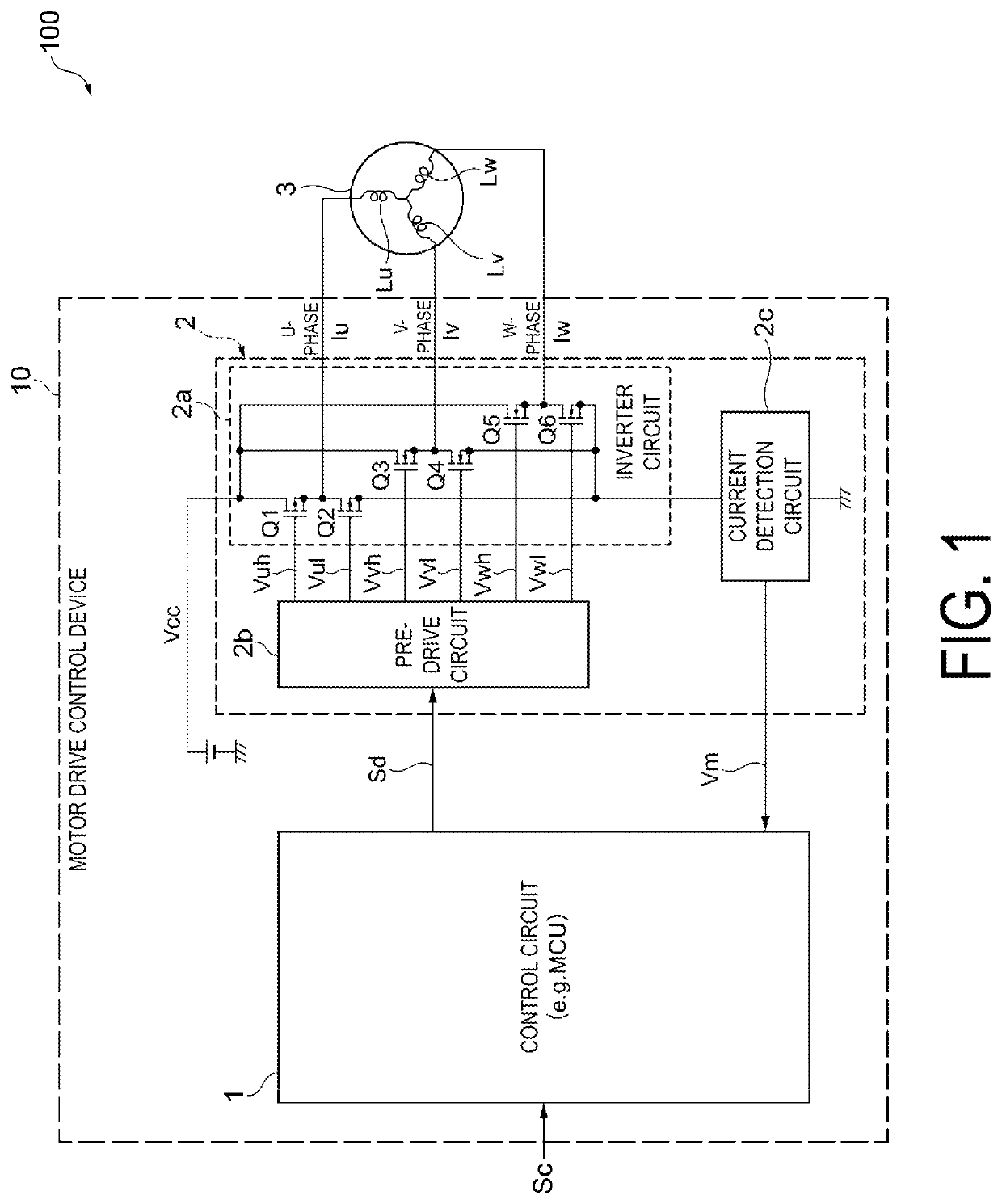
CROSS-REFERENCE TO RELATED APPLICATIONS[0001]This application claims the benefit of Japanese Application No. JP2020-175521 filed on Oct. 19, 2020, the entire disclosure of which is hereby incorporated herein by reference.TECHNICAL FIELD[0002]The present invention relates to a motor drive control device and a motor drive control method.BACKGROUND ART[0003]In general, permanent magnet synchronous motors (PMSMs) serving as brushless DC motors are roughly classified into a surface permanent magnet synchronous motor (SPMSM) having a permanent magnet attached to the surface of a rotating element, and an interior permanent magnet synchronous motor (IPMSM) having a permanent magnet embedded in a rotating element.[0004]Furthermore, a known method of controlling a permanent magnet synchronous motor (PMSM) is a sensorless vector control method including estimating the rotation angle and rotation speed of a rotating element (rotor) of a motor to control drive of the motor without using a sensor...

Claims


Application Information

Patent Timeline
IPC IPC(8): H02P21/18H02P21/24H02P21/34H02P23/12H02P6/18
CPCH02P21/18H02P21/24H02P2207/05H02P23/12H02P6/18H02P21/34H02P21/13H02P21/22H02P6/28H02P25/022H02P2207/055
Inventor KOKUBO, HIROKITOTSUKA, SHINJIMASUDA, SHIGEMI
Owner MINEBEAMITSUMI INC
Why Eureka
Try Eureka