Device for securing a pneumatic spring with an acoustic decoupling function

a technology of acoustic decoupling and a pneumatic spring, which is applied in the direction of screws, shock absorbers, washers, etc., can solve the problems of reducing the effective connection surface of components, unfavorable noise reduction, and complicated screw connection of this acoustic bearing during assembly, so as to improve the effect of acoustic decoupling

Pending Publication Date: 2022-04-21
CONTINENTAL TEVES AG & CO OHG
View PDF1 Cites 0 Cited by
  • Summary
  • Abstract
  • Description
  • Claims
  • Application Information

AI Technical Summary

Benefits of technology

[0008]It is therefore an object of the present application to improve the acoustic decoupling in the case of the fastening of an air spring to a portion of a motor vehicle body.
[0011]In order to prevent direct metallic contact in the case of the attachment of the air spring cover to the body portion, as a result of the use of suitable plastics materials according to the present application, a reflection effect at the boundary surfaces of the contacting components is utilized during the transmission of structure-borne sound waves. In this case, the first and the second plastics part are in the force path of the attachment in such a way that the structure-borne sound waves transmitted from the air spring cover to the fastening means are inhibited during the propagation into the body portion. In this case, this construction reduces the effective connected surfaces of the components and ensures that the fastening means is spaced apart from the body portion. The effective surface for the transmission of structure-borne sound is thus reduced significantly by the geometric configuration of the first and second plastics part. In addition, the different material properties of plastic compared with metal have a sound-reducing effect.
[0012]The achievement of the mechanical decoupling of the fastening means and the body portion by way of the use of two plastics parts also leads to a considerable weight reduction and thus also to a reduction in costs. Furthermore, there are versatile geometric design possibilities for the construction according to the present application.
[0014]According to another preferred embodiment, the second plastics part is a ring which is pushed onto the fastening means, and which terminates flush with the air spring cover, in such a way that the ring and the air spring cover bear against the body portion. In this configuration, the ring as second plastics part is embedded in the air spring cover, and therefore both ring and air spring cover bear with their upper side against the lower side of the body portion in an areal manner. This solution does not increase the axial installation space requirement, and likewise ensures acoustic decoupling. In this case, it is important that the ring lies in the axial force path of the fastening means and the securing element.
[0016]According to a further preferred embodiment, the first plastics part is a disk. This disk serves as a preload element and ensures that there is a sufficient preload force for fixing the securing element to the fastening means in an adequate manner. It also ensures that the securing element, which is manufactured from metal, is spatially spaced apart from the body portion, with the result that there is no direct metallic contact. The disk is likewise geometrically designed in such a way that the effective surface contact with respect to the body portion is as small as possible, in order to ensure the greatest possible reflection of the structure-borne sound waves.
[0018]According to a further preferred embodiment, the first and / or the second plastics part are / is manufactured from a thermoplastic. In order to ensure a sufficient preload of the first plastics part, in particular radiation-crosslinked thermoplastics are advantageous since these have a high creep behavior. This ensures that the preload of the fastening means does not decrease to an impermissible extent over the service life.

Problems solved by technology

Owing to the chassis operation, structure-borne sound waves are introduced into the body, which constitute an unpleasant source of noise.
However, the screw connection of this acoustic bearing is elaborate and awkward during assembly.
In this case, this construction reduces the effective connected surfaces of the components and ensures that the fastening means is spaced apart from the body portion.

Method used


Image

  • Device for securing a pneumatic spring with an acoustic decoupling function
  • Device for securing a pneumatic spring with an acoustic decoupling function

Examples


Embodiment Construction

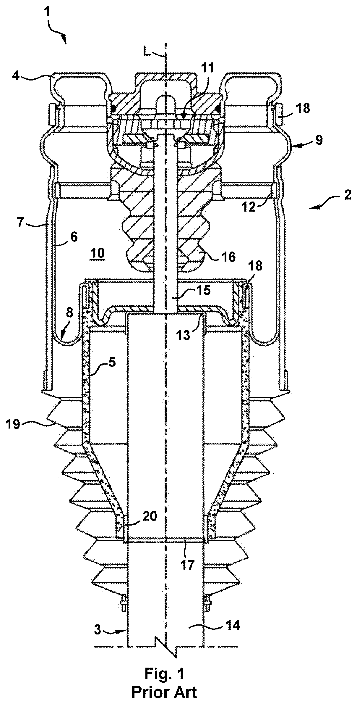
[0028]FIG. 1 shows a known air spring strut 1 having the essential components, namely air spring 2 and shock damper 3, wherein the air spring 2 comprises an air spring cover 4, a rolling piston 5 and a rolling bellows 6 with an outer guide 7 which encloses it in the manner of a sleeve. The shock damper 3 is provided within the air spring 2, the shock damper 3 comprising a damper tube 14, a piston rod 15 which can dip into the latter, and a damper bearing 11.

[0029]The air spring strut 1 satisfies two functional areas: on the one hand, the air spring 2 generates the carrying force, while the shock damper 3 is responsible for linear guidance. Fastening means on the air spring cover 4 make it possible for the air spring strut 1 to be fastened on the one hand to a motor vehicle body and on the other hand, via a shock damper eye (not illustrated), to a wheel carrier of the motor vehicle chassis, with the result that the motor vehicle is sprung and damped.

[0030]This regular installed posit...


PUM


Abstract

A device for fastening an air spring to a body portion of a motor vehicle, at least comprising an air spring cover, wherein the air spring cover comprises at least one fastening means, by means of which the air spring can be connected to the body portion of the motor vehicle, wherein, for attachment of the air spring, the fastening means is plugged through an opening of the body portion and is fixed to said body portion in a force-fitting manner by a securing element, wherein a first and a second plastics part are provided for acoustic decoupling of the air spring, wherein the first plastics part, is clamped between the body portion and the securing element, and the second plastics part is provided so as to be positioned below the body portion.

Description

CROSS-REFERENCE TO RELATED APPLICATIONS[0001]The present application is a National Stage Application under 35 U.S.C. § 371 of International Application No. PCT / EP2020 / 052549 filed on Feb. 3, 2020, which claims priority from German Patent Application No. 10 2019 201 357.0 filed on Feb. 4, 2019, in the German Patent and Trade Mark Office, the disclosures of which are herein incorporated by reference in their entireties.BACKGROUND1. Field[0002]The present application relates to a device for fastening an air spring to a body portion of a motor vehicle.2. Description of Related Art[0003]An air spring is arranged between the motor vehicle chassis or a wheel carrier and the motor vehicle body and thereby performs the function of cushioning the wheel. The air spring substantially consists of an air spring cover, a rolling piston and a rolling bellows clamped therebetween in an airtight manner, thereby delimiting a working chamber under air pressure. The rolling bellows is enclosed by a slee...

Claims


Application Information

Patent Timeline
Patent Type & Authority Applications(United States)
IPC IPC(8): B60G11/28
CPCB60G11/28B60G2202/152B60G2600/44B60G2206/7104B60G2204/126B60G15/14B60G2206/424B60G2204/41F16F9/0454B60G2206/73F16F9/54F16F9/084F16B35/041F16B43/001F16B5/0241F16B37/04
Inventor RAUTENBERG, KAI MARCUS
Owner CONTINENTAL TEVES AG & CO OHG
Why Eureka
Try Eureka