


Quick Research
Generate reliable direction feasibility study reports for your R&D in just a few steps.

Technical Q&A
Discover and master advanced knowledge NOW. Basics, ideas, possibilities, all at once.

Find Solutions
As an expert in R&D theories, this can generate solutions to your technical problems instantly.

Evaluate Feasibility
Analyze your overall solution with one click, know your potential R&D risks in advance.

Monitor Landscape
Get weekly tech updates, stay abreast of the latest tech innovations and key insights.
Veress-type needles with illuminated guidance and safety features
a technology of illuminated guidance and safety features, applied in the field of instruments, can solve problems such as inadvertent injury to internal organs such as bowels and major blood vessels
- Summary
- Abstract
- Description
- Claims
- Application Information
AI Technical Summary
Benefits of technology
Problems solved by technology
Method used
Image

Examples
second embodiment
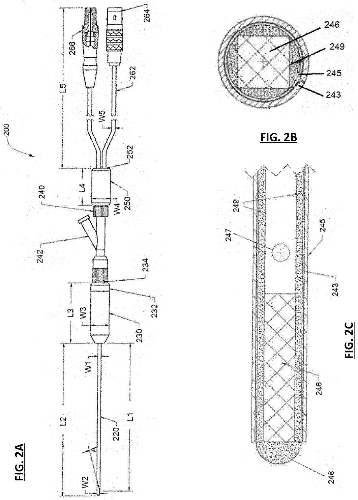
[0069]In further accordance with the disclosure, a visualization insufflation needle assembly 200 is presented in FIGS. 2A-2C. With reference to FIG. 2A, the assembly includes an outer sheath 220 with an angled, sharpened distal tip for penetrating tissue, including a spring loaded visualization stylet, similar to that in FIGS. 1A-1B. The outer sheath can be made, for example, from stainless steel tubing, and have a length L1 between for example, about 2 and about 6 inches, in increments of about one eighth of an inch. Visualization stylet can have a similar length L2. The diameter, or width, W2, of the visualization stylet can be, for example, between about 0.050 to about 0.1 inches in increments of 0.01 inches. The sheath can have a diameter or width W1 between about 0.06 and 0.12 inches, in increments of 0.01 inches. The distal tube 220 is attached at a proximal end to a cannula body 230 with a cannula cap 232 that may be removable. A spring biasing mechanism similar in functiona...
first embodiment
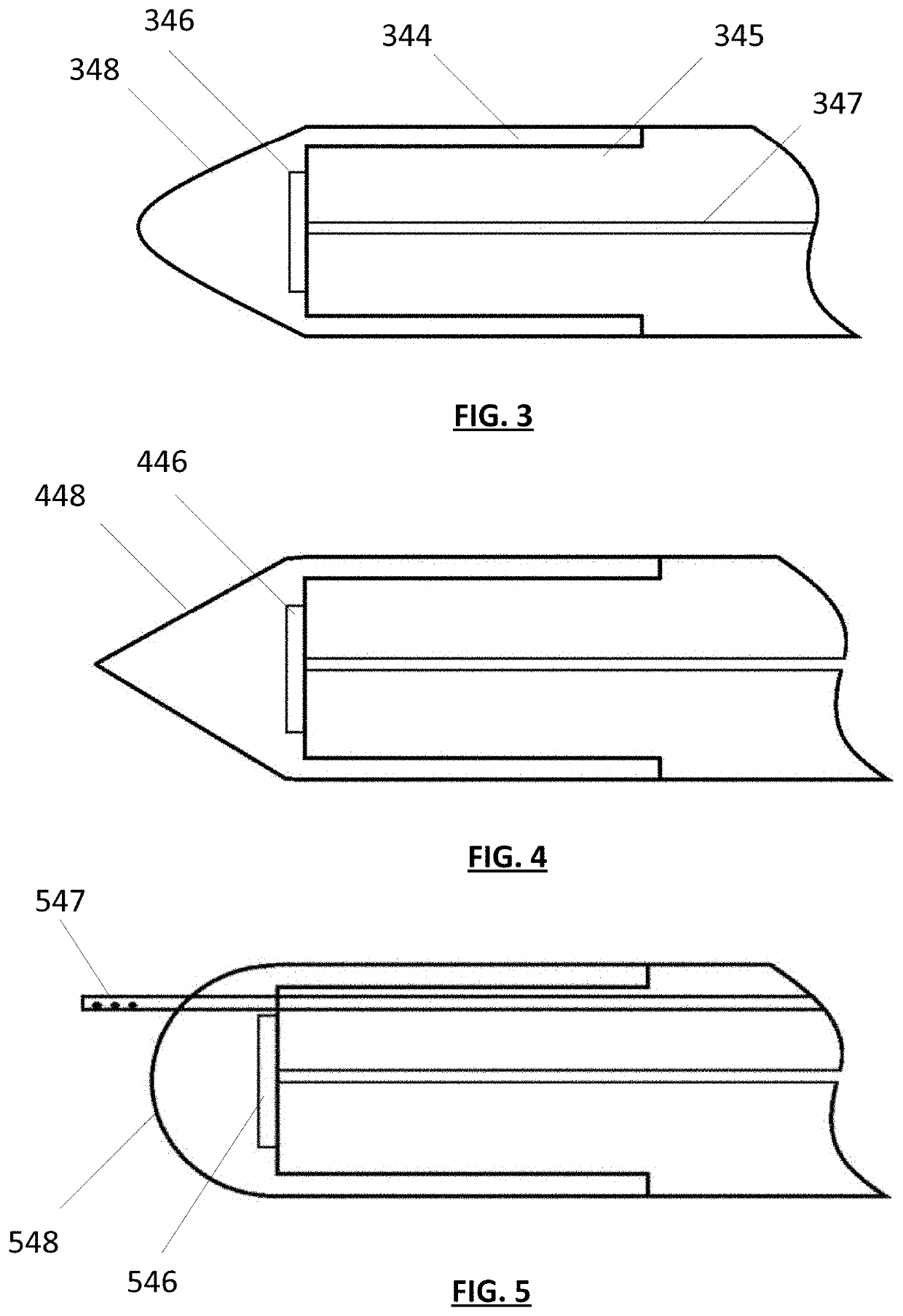
[0073]FIG. 5 is similar to the embodiments of FIGS. 3 and 4, but includes a dome shaped lens 548, and photodetector 546 and the like. Additionally, the embodiment of FIG. 5 includes a lens flushing mechanism that includes a tubular body 547 directed through the body of the visualization stylet that includes a plurality of flushing holes. The body 547 can be formed from a hypotube, for example, with a sealed distal tip and one or more transversely formed holes through the hypotube to direct a fluid jet across the lens, wherein the fluid can include, for example, saline, another liquid and / or a gaseous substance, such as carbon dioxide insufflation gas. Tube 547 is preferably slidably movable with respect to visualization stylet, and can be controllably deployed by advancing it distally with respect to the visualization stylet distal tip. In one embodiment, the tube 547 is made from a shape memory material (e.g., Ni Ti alloy) wherein it is heat set to bend around the tip to direct cle...
embodiment 1700
[0084]FIGS. 17A is an isometric view of an optical trocar assembly 1700 in accordance with the present disclosure. FIG. 17B is a close up view of a distal end portion of device 1700. As depicted, device 1700 includes a proximal handle portion 1750 that may be removably coupled to a distal cannula 1710. Distal cannula 1710 includes a proximal handle portion that is coupled to a distal shaft 1712. Shaft 1712 is hollow, has a distal end portion 1714, and is configured to receive an elongate removable sheath 1720 therein. An annular gap can be defined between the inner surface of the lumen defined through the shaft 1712, and the external surface of the sheath 1720. A flushing assembly 1760 is provided that includes an input port, a valve, and an output port that directs liquid or other beneficial agent to a cavity defined between the cannula 1710 and the handle 1750, resulting in fluid being directed between shaft 1712 and sheath 1720, or between shaft 1712 and optical probe 1780, discu...
PUM
 Abstract
Description
Claims
Application Information
 - R&D Engineer
- R&D Manager
- IP Professional
- Industry Leading Data Capabilities
- Powerful AI technology
- Patent DNA Extraction
Browse by: Latest US Patents, China's latest patents, Technical Efficacy Thesaurus, Application Domain, Technology Topic, Popular Technical Reports.
© 2024 PatSnap. All rights reserved.Legal|Privacy policy|Modern Slavery Act Transparency Statement|Sitemap|About US| Contact US: help@patsnap.com