
Micro-robot control apparatus

a technology of control apparatus and micro-robots, applied in the field of micro-robot control apparatus, can solve the problems of increasing power consumption, inefficient in various operations, and inability to provide efficient installation and operation of devices, so as to reduce the number of power supplies, simplify the device, and ensure the effect of efficiency

Pending Publication Date: 2022-03-03
KOREA INST OF MEDICAL MICROROBOTICS
View PDF0 Cites 16 Cited by
  • Summary
  • Abstract
  • Description
  • Claims
  • Application Information

AI Technical Summary

Benefits of technology

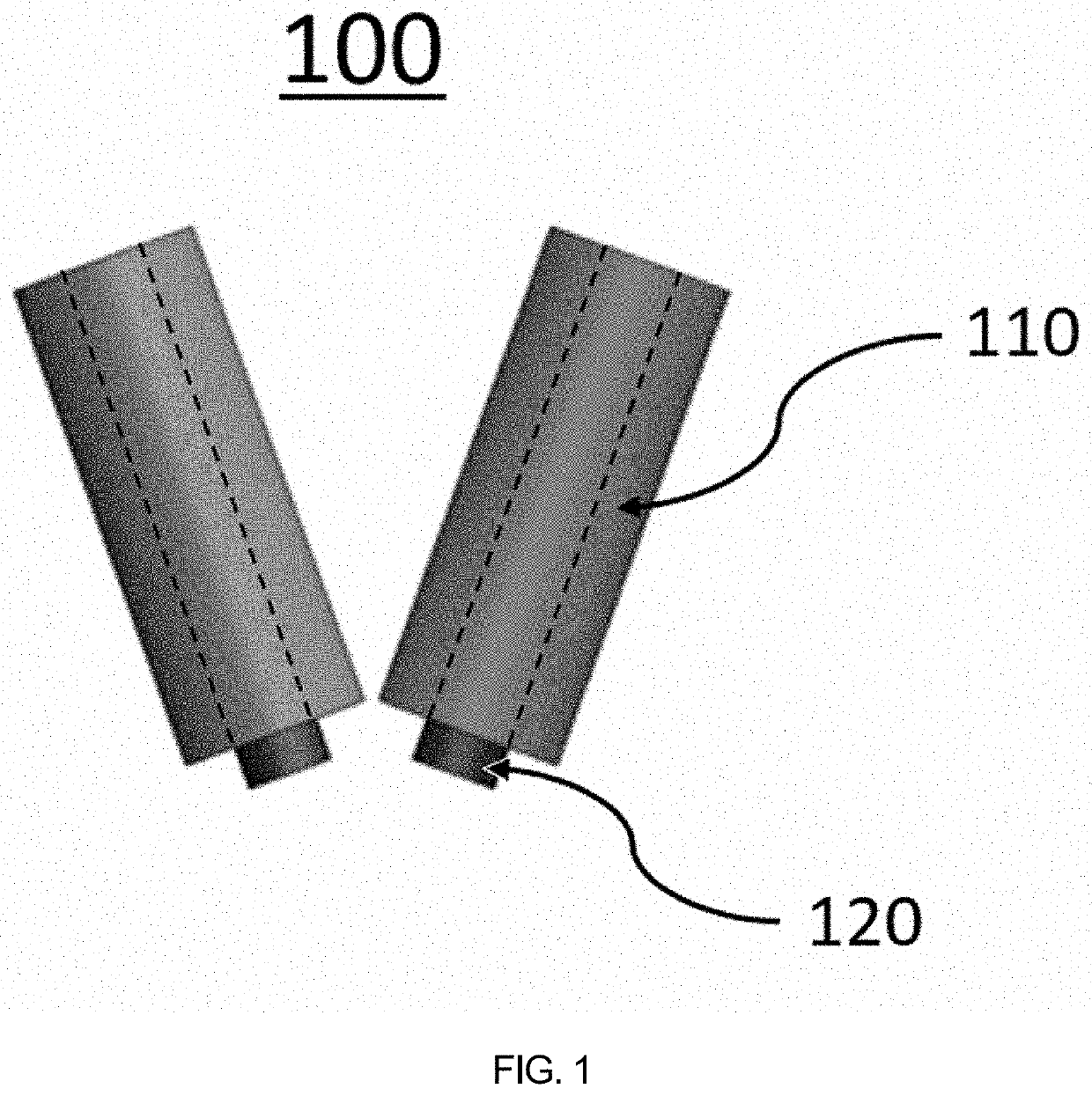
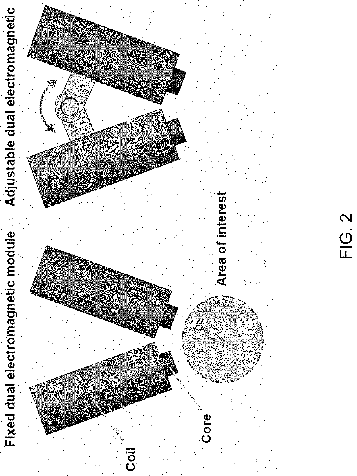
The present patent is about a micro-robot control apparatus that uses a dual electromagnetic module to focus a magnetic field on the area of interest where the magnetic field is desired to be focused. This simplifies the device and makes it easier to install and operate in the surgery area. The apparatus also reduces the number of power supplies and power consumption by reducing the number of electromagnets. Additionally, the apparatus enables simultaneous generation of wireless power and location recognition of the micro-robot using an external magnetic induction transmission coil and a magnetic induction frequency signal reception coil of the micro-robot. The apparatus can recognize the location of the micro-robot in 6 degrees of freedom using locations in three directions and angles in three directions, which solves the locational errors caused by the human body and sensor device characteristics.

Problems solved by technology

Existing electromagnetic field driving devices have a large number of electromagnets in use and thus are large in size, thereby failing to provide efficient installation and operation of the devices.
Further, the large number of electromagnets causes an increase in the number of power supplies, thereby resulting in an increase in power consumption, which is inefficient in terms of various operations.
In addition, a magnetic field driving device using permanent magnets has a small number of magnets in use, but has a limitation in controlling a micro-robot.
Further, the robot is driven through a change of the distance between the robot and the magnet and a change of the direction of the magnet, and since the permanent magnet has a constant magnetization value, there is limited control performance.
Although a control space of the permanent magnet is secured using a motor, it is difficult to control the magnetic field in real time due to the time difference in the movement by the motor.
In the case of a conventional method of controlling a robot by changing a gradient magnetic field and a uniform magnetic field in space, it is difficult to focus the robot to a desired location without location information.
In addition, since the micro-robot (a capsule endoscope or the like) inserted into the human body is configured in micro units depending on the purpose, if the micro-robot is inserted into the human body, it is difficult to recognize the exact location of the capsule endoscope while it moves.
In particular, in order to recognize the location of the capsule endoscope inside the human body, a technology for recognizing the location of the capsule endoscope using RF (radio frequency) signals is being developed, but this technology has a problem with location errors because the transmission characteristics of RF signals through the human body differ.
Although a location recognition technology is being developed through an array of Hall sensors for measuring magnetic field components, efficiency of measuring the magnetic field is lowered depending on the distance between the Hall sensor and the capsule, thereby causing location errors.
However, location recognition using the X-ray information requires a large configuration of a system, which increases the cost.

Method used


Image

  • Micro-robot control apparatus
  • Micro-robot control apparatus
  • Micro-robot control apparatus

Examples


Embodiment Construction

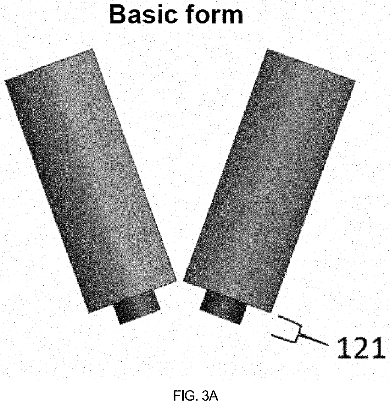
[0061]An electromagnetic module for focusing a magnetic field may include two electromagnetic modules including a magnetic core configured as a paramagnet and a solenoid coil wound around the magnetic core, wherein the two electromagnetic modules are disposed to be symmetrical with each other with respect to an imaginary symmetric axis passing through the center of an area of interest, where the magnetic field is desired to be focused, on a two-dimensional plane including the symmetric axis.

DETAILED DESCRIPTION

[0062]Hereinafter, a detailed description of a preferred embodiment of the present disclosure will be described with reference to the accompanying drawings. In the following description of the present disclosure, if it is determined that a detailed description of a related known function or configuration may unnecessarily obscure the subject matter of the present disclosure, a detailed description thereof will be omitted.

[0063]Since embodiments according to the concept of the ...


PUM


Abstract

The present invention relates to a micro-robot control apparatus. An electromagnetic module for focusing magnetic field and a micro-robot control apparatus comprising the electromagnetic module, according to the present invention, focus the magnetic field in an area of interest where focusing of same is desired to allow a micro-robot to be controlled, and, the apparatus having been simplified, allow efficient setup and operation in the surgery area. Moreover, the number of electromagnets is reduced to thus reduce the number of sources of power, thereby resulting in efficient operation of the apparatus with lowered power consumption. Additionally, by means of a magnetic induction frequency signal reception coil of the micro-robot and the external micro-robot control apparatus equipped with a magnetic induction transmission coil, the micro-robot control apparatus can both generate power wirelessly for the micro-robot, and implementation location recognition of same due to the efficiency of the generated power.

Description

TECHNICAL FIELD[0001]The present disclosure has been made according to project number HI19C0642 under the support of the Ministry of Health and Welfare, the research management institution for the above project is the Korea Health Industry Development Institute, the title of the research business is “Development of Technology and Commercialization for Medical Micro-robots”, the title of the research project is “Common Basis Technology Development Center for Commercialization of Medical Micro-robots”, the host organization thereof is the Korea Institute of Medical Micro-robotics, and the research period thereof is Jun. 12, 2019 to Dec. 31, 2022.[0002]This patent application claims priority from Korean Patent Application No. 10-2019-0019443, filed with the Korean Intellectual Property Office on Feb. 19, 2019, which is hereby incorporated by reference.[0003]This patent application claims priority from Korean Patent Application No. 10-2019-0166881, filed with the Korean Intellectual Pro...

Claims


Application Information

Patent Timeline
Patent Type & Authority Applications(United States)
IPC IPC(8): A61B1/04A61B1/00A61B1/045A61B34/00
CPCA61B1/041A61B1/00158A61B34/72A61B1/045A61B1/00036A61B17/00A61B34/20A61B34/30A61M25/01B25J13/00A61B2034/303A61B34/73A61B2034/731A61B2034/2051A61B2090/3762A61B2090/376A61B2017/00221
Inventor PARK, JONGOHKIM, CHANG-SEICHOI, EUNPYOKIM, JAYOUNGKANG, BYUNGJEONHOANG, MANH CUONGHONG, AYOUNG
Owner KOREA INST OF MEDICAL MICROROBOTICS
Learn More