Gas Compression Process

Pending Publication Date: 2022-02-10
BELL ENG INC
View PDF0 Cites 0 Cited by
  • Summary
  • Abstract
  • Description
  • Claims
  • Application Information

AI Technical Summary

Benefits of technology

The patent describes a method for compressing and cooling gas, particularly carbon dioxide, using a multi-stage compressor system. The gas is first compressed in a plurality of pairs of displacer vessels, then cooled using a plurality of discharge coolers. The cooled gas is then compressed in a linear configuration using a series of stages until it reaches a desired pressure. The compressed gas is then collected and pressurized using a plurality of pumps before being sent to a pipeline. The method can be used to compress and cool the gas from ethanol production facilities, and the compressed gas can be recompressed for use in enhanced oil recovery. The technical effects of the patent include improved gas compression and cooling efficiency, reduced energy consumption, and improved operational flexibility.

Problems solved by technology

Incompressible liquids can be very harmful to mechanical compressors.

Method used


Image

  • Gas Compression Process
  • Gas Compression Process
  • Gas Compression Process

Examples


Embodiment Construction

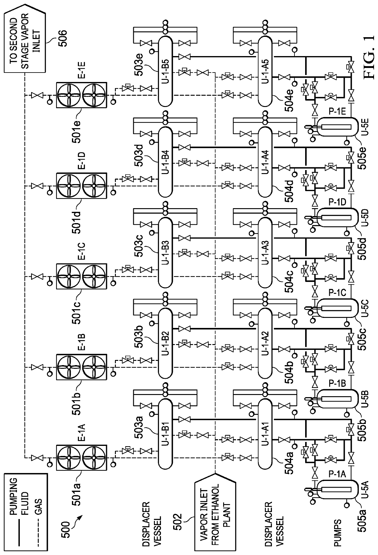
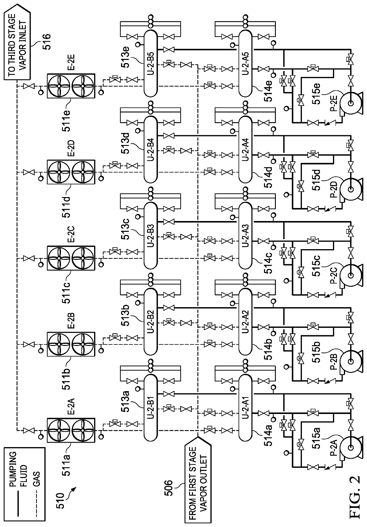
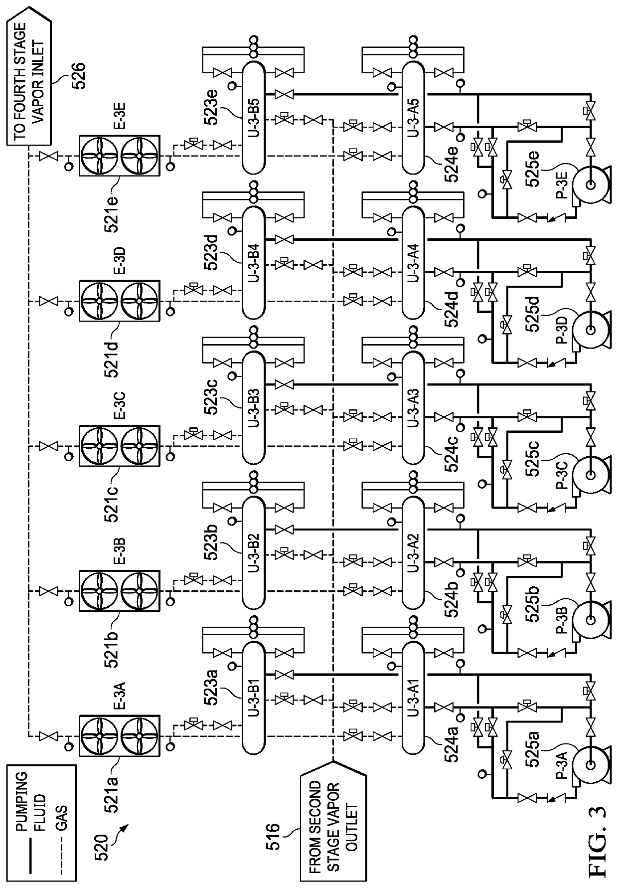
[0003]An example embodiment may include a method for compressing gas comprising compressing a gas at a first stage compressor to create a first compressed gas, cooling the first compressed gas, compressing the first compressed gas at a second stage compressor to create a second compressed gas, cooling the second compressed gas, compressing the second compressed gas at a third stage compressor to create a third compressed gas, cooling the third compressed gas, compressing the third compressed gas at a fourth stage compressor to create a fourth compressed gas, cooling the fourth compressed gas, condensing the fourth compressed gas into a liquified gas, collecting the liquified gas, pressuring the liquified gas, delivering the liquified gas into a gas line.

[0004]A variation of the example embodiment may include the gas being CO2. The first stage compressor may be a plurality of pairs of displacement vessels each pair having a dedicated pump. The second stage compressor may be a plurali...


PUM


Abstract

Example embodiments for a method for compressing gas into a liquified gas using a plurality of pairs of liquid gas displacers in parallel moving a working fluid between each pair of displacers to pressurize the gas, arranging sets of the parallel liquid gas displacers in a series to raise the pressure, directly cooling the gas at each displacer pair, and finally condensing the gas using a coolant, collecting the liquified gas, and pressurizing the liquified gas for use in a pipeline.

Description

RELATED APPLICATIONS[0001]This application claims priority to U.S. Provisional Application No. 63 / 061,049, filed Aug. 4, 2020 and U.S. Provisional Application No. 63 / 061,059, filed Aug. 4, 2020.BACKGROUND OF THE INVENTION[0002]To summarize the technology historically utilized in gas compression processes involving low first stage suction pressures would be using a reciprocating or centrifugal compressor to increase the pressure in stages. The pressure increase per stage is limited by the heat of compression temperature increase with material of construction limits of around 225 F. Scrubber vessels are located prior to the inlet of each stage to prevent liquids from entering the compressor. Incompressible liquids can be very harmful to mechanical compressors. The heat of compression is removed from the gas after each stage of compression, usually by an air-cooled exchanger. Some condensation of liquids is common during the cooling of the vapor, so a two-phase separator is located aft...

Claims


Application Information

Patent Timeline
IPC IPC(8): F25J1/00
CPCF25J1/0052F25J2230/30F25J1/0027F04B23/04F04F1/06F04F1/12F04B15/08F04B2015/0818
Inventor RICHARDSON, ROBERTBRIGGS, TYLER
Owner BELL ENG INC
Why Eureka
Try Eureka