Squeeze container liquid extrusion tool

Active Publication Date: 2016-06-23
BELANGER RICHARD A
View PDF61 Cites 4 Cited by
  • Summary
  • Abstract
  • Description
  • Claims
  • Application Information

AI Technical Summary

Benefits of technology

The patent text explains how squeeze bottles work and how the design of the bottle and the size of the nozzle can affect the speed at which the liquid levels out after use. The text also explains how air can be trapped behind the liquid and increase pressure when the bottle is squeezed. The text concludes by mentioning that giving the user the ability to adjust the relationship between the liquid viscosity and the orifice of preference would improve the user's experience. The technical effect would be to allow users to better control the product by adjusting the speed at which the liquid levels out after use and to make the user experience more comfortable by allowing air to re-enter the bottle faster or slower as desired.

Problems solved by technology

The above-described caulk guns and hot-melt glue guns of the prior art all lack the ability to be used with glue or other flowable liquids contained in a squeeze bottle.
Hot met glue guns advance a stick of solid adhesive into a heated nozzle where it melts, but a hot melt glue gun could not be used with liquid adhesive or a squeeze bottle.
Also, unlike caulking tubes, which dispense caulk by a plunger pushing the caulk through the tube from the rear end, products contained in squeeze bottles are dispensed by a force applied to the sidewall or body of the squeeze bottle, therefore increasing the pressure inside the squeeze bottle and causing the product to flow through the nozzle or cap.
These condiment bottles generally offer a better overall experience than an old fashioned glass bottle, but they introduce other irritating issues to the process.
This type of solution is decidedly not appropriate for adhesives of a lower viscosity and most similar liquids.

Method used


Image

  • Squeeze container liquid extrusion tool
  • Squeeze container liquid extrusion tool
  • Squeeze container liquid extrusion tool

Examples


Embodiment Construction

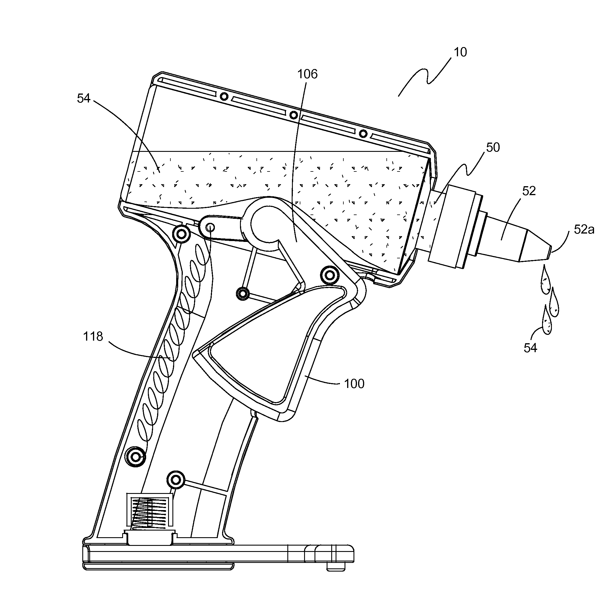
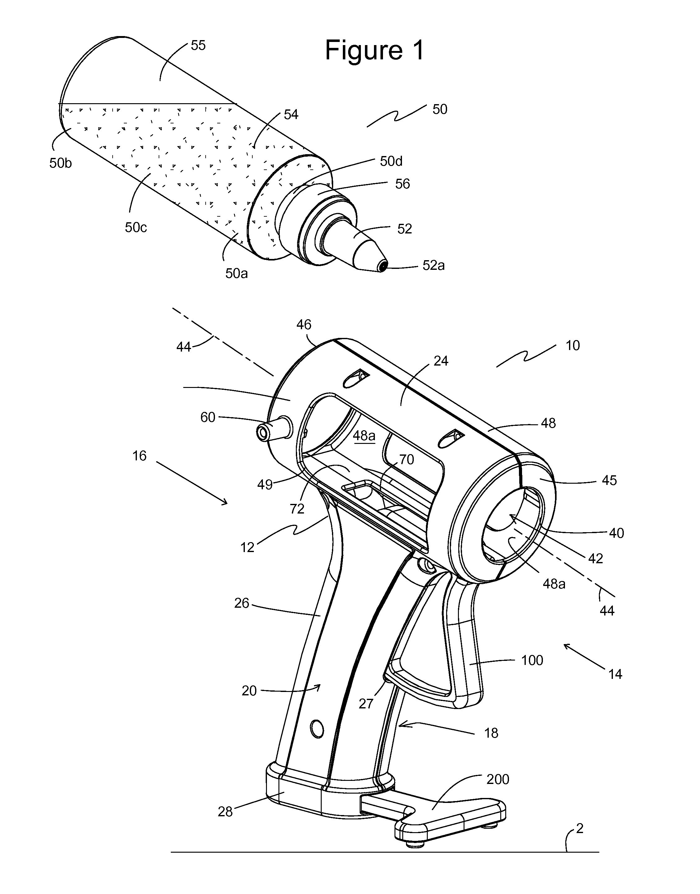
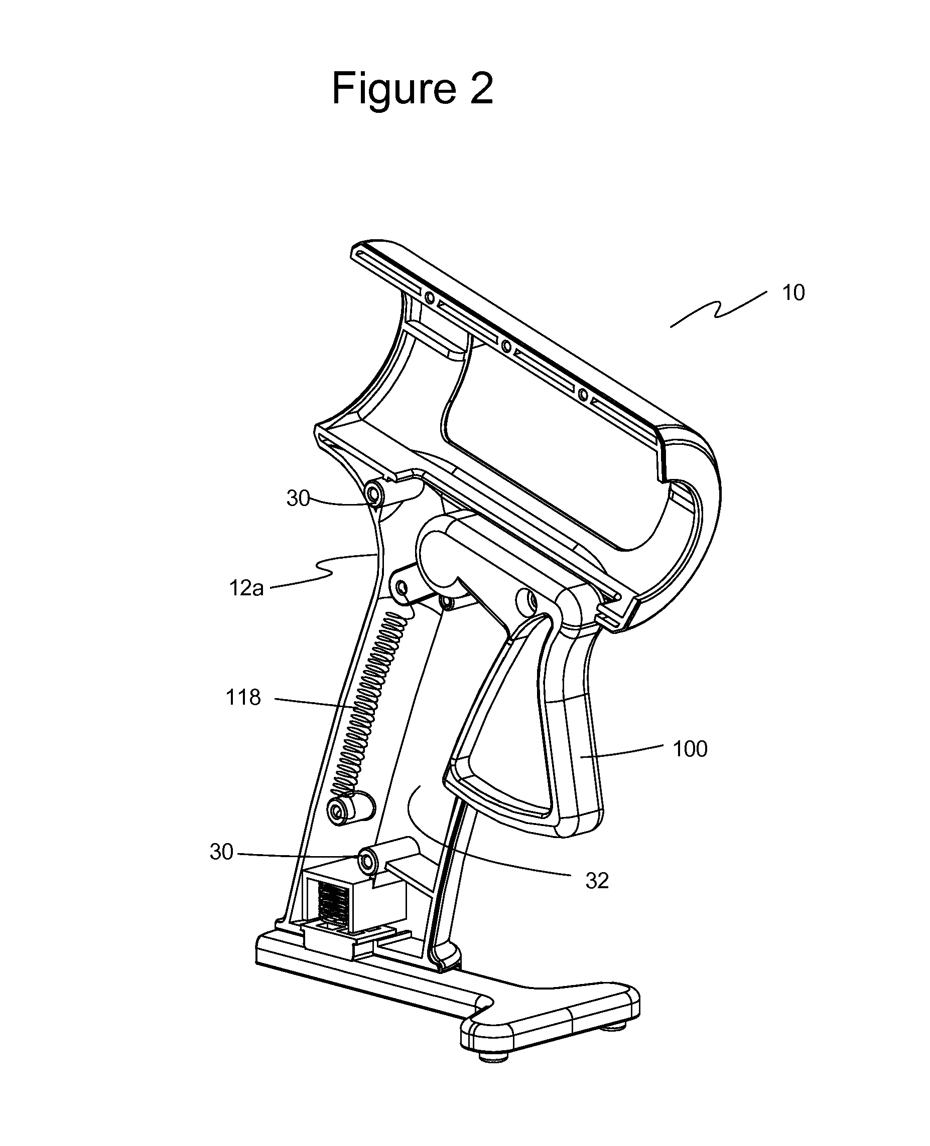
[0045]The preferred embodiments of the present invention are illustrated in FIGS. 1-11. FIG. 1 illustrates a front, top, and side perspective view of one embodiment of an extrusion tool 10 usable with a liquid or other flowable product 54 contained in a squeeze container 50. Squeeze container 50 may be, for example, a bottle, a tube, or other type of container. Extrusion tool 10 has a dispenser body 12 with a front portion 14, a rear portion 16, a first side portion 18, and a second side portion 20. Dispenser body 12 includes a container-receiving portion 24, a handle portion 26, and a base portion 28, where the handle portion 26 is connected to and extends between container-receiving portion 24 and base portion 28. A trigger 100 is operatively connected to dispenser body 12.

[0046]Container-receiving portion 24 has a front end 45 that defines a forward-facing aperture 40. Container-receiving portion 24 has a peripheral sidewall 48 that defines container well 42 extending longitudina...


PUM


Abstract

An extrusion tool includes a dispenser body having a handle portion, a container-receiving portion, and a base portion. The handle portion is connected to and extends between the container-receiving portion and the base portion. The container-receiving portion defines a forward-facing aperture and a container well extending along a container well axis, where the container well is constructed and arranged to receive and retain a squeeze container with a nozzle of the squeeze container extending through the forward-facing aperture. A trigger is operatively connected to the dispenser body and movable between a non-dispensing position and a dispensing position. The trigger has a finger portion and a contact lever portion that is oriented to move into and out of the container well when the finger portion is moved between the non-dispensing position and the dispensing position.

Description

BACKGROUND OF THE INVENTION[0001]1. Field of the Invention[0002]The present invention relates generally to applicators and extrusion devices for liquids, pastes and the like. More particularly, the present invention relates to an extrusion tool for use with adhesives and other liquids that are extruded from a squeeze container.[0003]2. Description of the Prior Art[0004]It has long been desirable to be able to dispense liquid products in a controlled manner, whether that product is glue, caulk, a lubricant, frosting, ketchup, paint, thixotropic resins, or any of a variety of similar liquids, gels, and flowable substances that could be extruded from a squeeze container.[0005]One prior art applicator is a caulking gun used with tubes of construction adhesive, caulk, and grease. The caulking gun has an elongated, hollow cylindrical frame that is sized to receive tubes of caulk and the like, where the tube has an extended tip and a piston that can be advanced into and along the tube to e...

Claims


Application Information

Patent Timeline
IPC IPC(8): B05C17/005B05C17/01
CPCB05C17/00596B05C17/0116B05C17/00583B05B11/048B05B15/62B05B12/002
Inventor BELANGER, RICHARD A.
Owner BELANGER RICHARD A
Why Eureka
Try Eureka