
Air intake housing and blower for a corresponding motor vehicle heating, ventilation and/or air conditioning device

a technology for air intake and motor vehicles, which is applied in the direction of liquid fuel engines, machines/engines, transportation and packaging, etc., can solve the problems of fogging and condensation of moisture in the recirculated air on the windshield, and achieve the effect of improving the “warm-up” of the interior air

Pending Publication Date: 2022-02-03
VALEO SYST THERMIQUES
View PDF4 Cites 0 Cited by
  • Summary
  • Abstract
  • Description
  • Claims
  • Application Information

AI Technical Summary

Benefits of technology

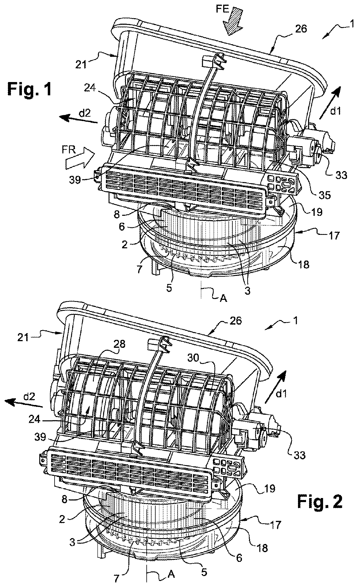
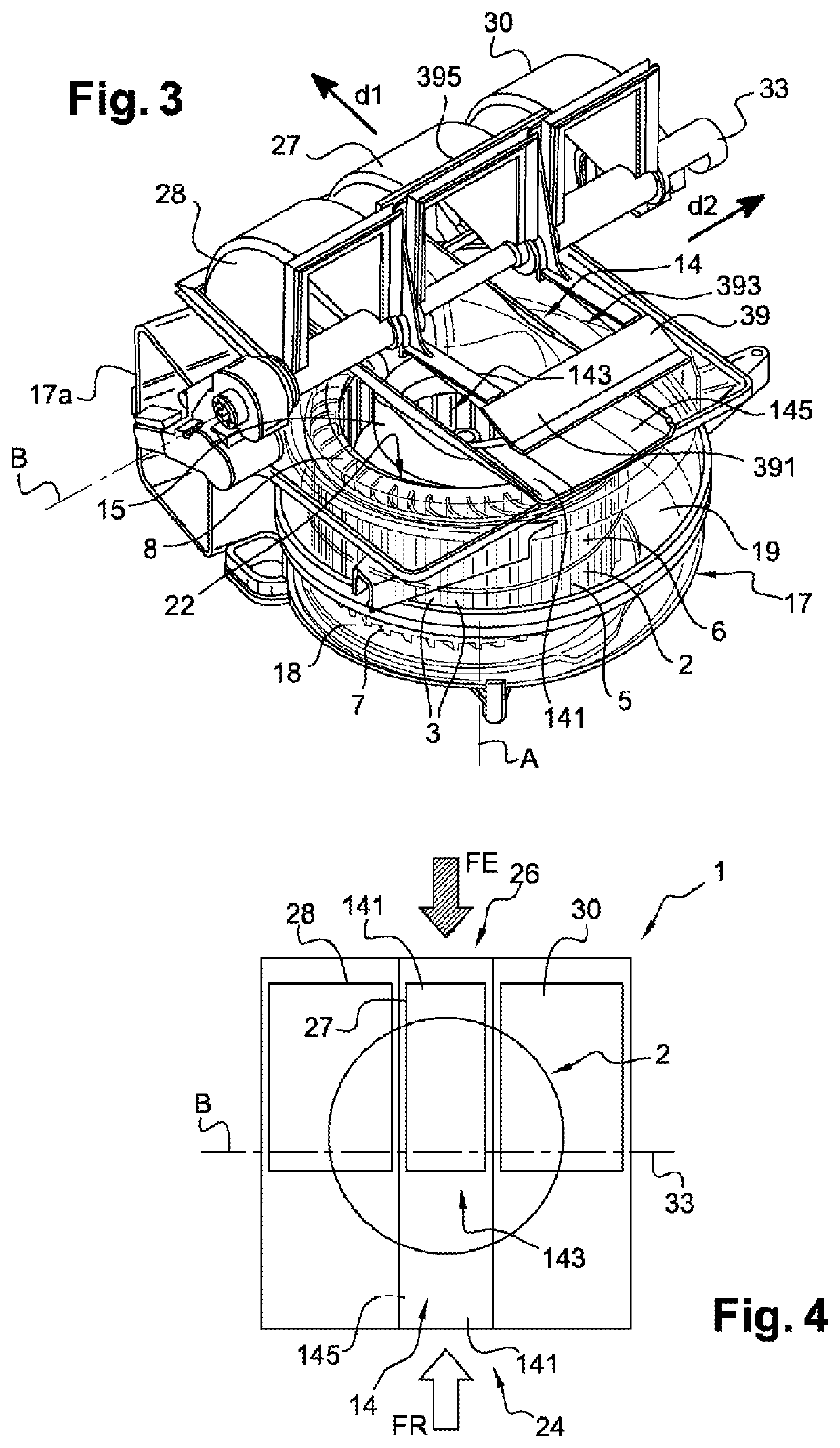
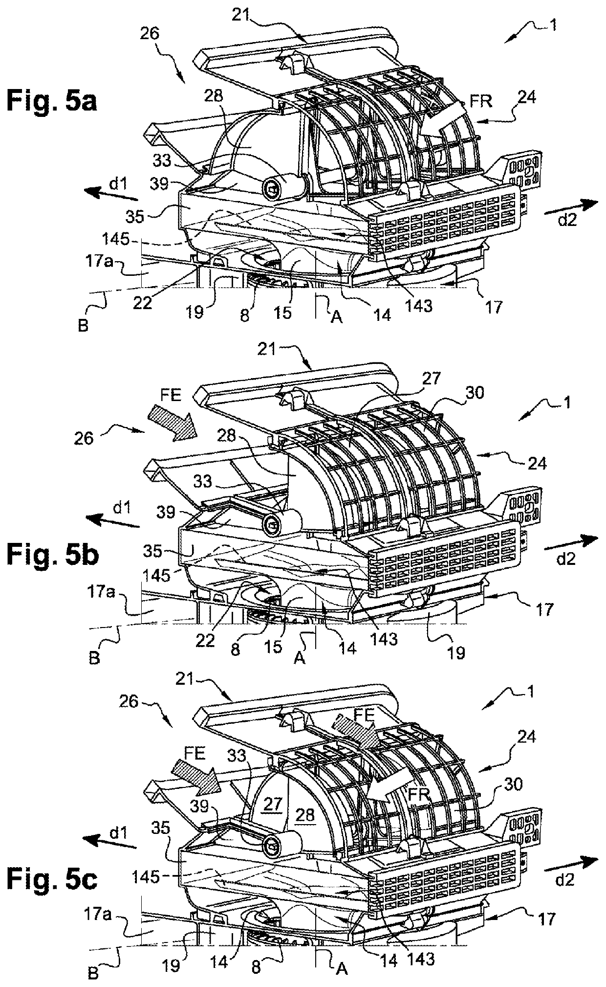
The invention proposes an alternative form of blower that improves the "warm-up" of the air in the interior of a vehicle. This is achieved by optimizing the proportion of air flow that enters and easily altering the quantities of recirculated air and exterior air. In cold weather, the central flap allows more recirculated air to enter, warming up the air more quickly while limiting the phenomena of fogging on the windshield. The larger dimensions of the central flap result in accelerated "warm-up" while avoiding fogging on the windshield.

Problems solved by technology

However, the recirculated air is more laden with moisture than the air coming from outside the vehicle, which means that, if the recirculated air is directed toward the windshield, via the ventilation openings situated in front of the driver or in front of the front-seat passenger, for example, or directly onto the windshield, the moisture contained in the recirculated air condenses on the windshield and creates fog.

Method used


Image

  • Air intake housing and blower for a corresponding motor vehicle heating, ventilation and/or air conditioning device
  • Air intake housing and blower for a corresponding motor vehicle heating, ventilation and/or air conditioning device
  • Air intake housing and blower for a corresponding motor vehicle heating, ventilation and/or air conditioning device

Examples


Embodiment Construction

[0065]The following embodiments are examples of the subject matter of the invention and are given by way of illustration. The invention is not restricted to these embodiments. Although the description refers to one or more embodiments, this does not necessarily mean that each reference relates to the same embodiment, or that the features apply only to one embodiment. Individual features of different embodiments can also be combined or interchanged in order to create other embodiments.

[0066]In the description, certain elements may be indexed, or in other words mention may be made for example of a first element of a second element. In this case, the indexing is simply used to differentiate and denote elements that are similar but not identical. This indexing does not imply a priority of one element with respect to another. Such denominations may easily be interchanged without departing from the scope of the present invention.

[0067]The invention relates to an air intake housing 21 for ...


PUM


Abstract

The invention relates to an air intake housing (21), in particular for a heating, ventilation and / or air conditioning device, comprising: —at least two distinct air inlets (24, 26), and —air guiding members (27, 28, 30) configured to direct at least one air flow that is intended to be admitted into the air intake housing (21). According to the invention, the air guiding members comprise at least three flaps (27, 28, 30), one of these being a central flap (27) and two lateral flaps (28, 30) arranged one on each side of the central flap (27), said flaps (27, 28, 30) being positioned between the said two distinct air inlets (24, 26) of the air intake housing (21) so as to be able to move about a single axis of pivoting (33). The invention also relates to a suction blower (1) comprising such an air intake housing (21) and to a corresponding heating, ventilation and / or air conditioning device.

Description

TECHNICAL FIELD OF THE INVENTION[0001]The present invention relates to an air intake housing and to an intake blower comprising such an air intake housing, intended for a motor vehicle heating, ventilation and / or air conditioning device. The invention also relates to a heating, ventilation and / or air conditioning device comprising such a blower.PRIOR ART[0002]A motor vehicle comprises an interior into which air, conventionally derived from a heating, ventilation and / or air conditioning device, emerges.[0003]The heating, ventilation and / or air conditioning device, also known by the abbreviation HVAC, may be supplied either with air external to the vehicle (also referred to as fresh air), or with recirculated air, which is to say air derived from the vehicle interior. In the known way, a blower is used to cause the airflow to circulate. This may be the flow of fresh or new air coming from outside the vehicle, or the flow of recirculated air coming from the vehicle interior, or else a ...

Claims


Application Information

Patent Timeline
Patent Type & Authority Applications(United States)
IPC IPC(8): B60H1/00F04D29/28
CPCB60H1/00471B60H1/00021B60H2001/00085F04D29/283B60H1/00664
Inventor PIERRES, PHILIPPEAILLOUD, FABRICEBARBIER, THIERRY
Owner VALEO SYST THERMIQUES
Learn More