
Pneumatic simulator apparatus for an open bolt automatic firearm

Pending Publication Date: 2022-01-20
DVORAK VOJTECH
View PDF0 Cites 0 Cited by
  • Summary
  • Abstract
  • Description
  • Claims
  • Application Information

AI Technical Summary

Benefits of technology

The present disclosure is about a device that can convert an open bolt automatic firearm into a training weapon. It uses compressed gas instead of live ammunition, which means it's a cost-effective way to fire a large number of rounds. The device cycles the weapon's firing mechanism just like it would with live ammunition, including recoil and identifying the point of impact. The device is powered by a cable or batteries and uses the same trigger as the actual weapon. It's easy to install and remove from the firearm without special tools. Overall, the device allows for safe and effective training with the real trigger and at a low cost.

Problems solved by technology

There may be a slight difference in performance when using CO2 gas.

Method used


Image

  • Pneumatic simulator apparatus for an open bolt automatic firearm
  • Pneumatic simulator apparatus for an open bolt automatic firearm
  • Pneumatic simulator apparatus for an open bolt automatic firearm

Examples


first embodiment

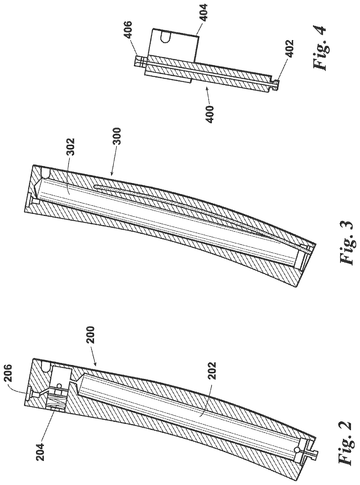
[0028]FIG. 2 is a cut-away side view of magazine 200 including a compressed gas (such as compressed air) reservoir 202 and pressure regulator 204 of the pneumatic simulator of the present disclosure.

second embodiment

[0029]FIG. 3 is a cut-away side view of a magazine 300 including a compressed gas (CO2) reservoir 302 of the pneumatic simulator of the present disclosure.

third embodiment

[0030]FIG. 4 is a cut-away side view of a magazine 400 including a gas supply fitting 402 from a remote compressed gas source, a locating block 404 to be inserted into the magazine well of the automatic firearm, and a quick connect gas fitting 406 which mates with nipple 124 of stationary piston 104 of FIG. 1 to supply compressed gas thereto.

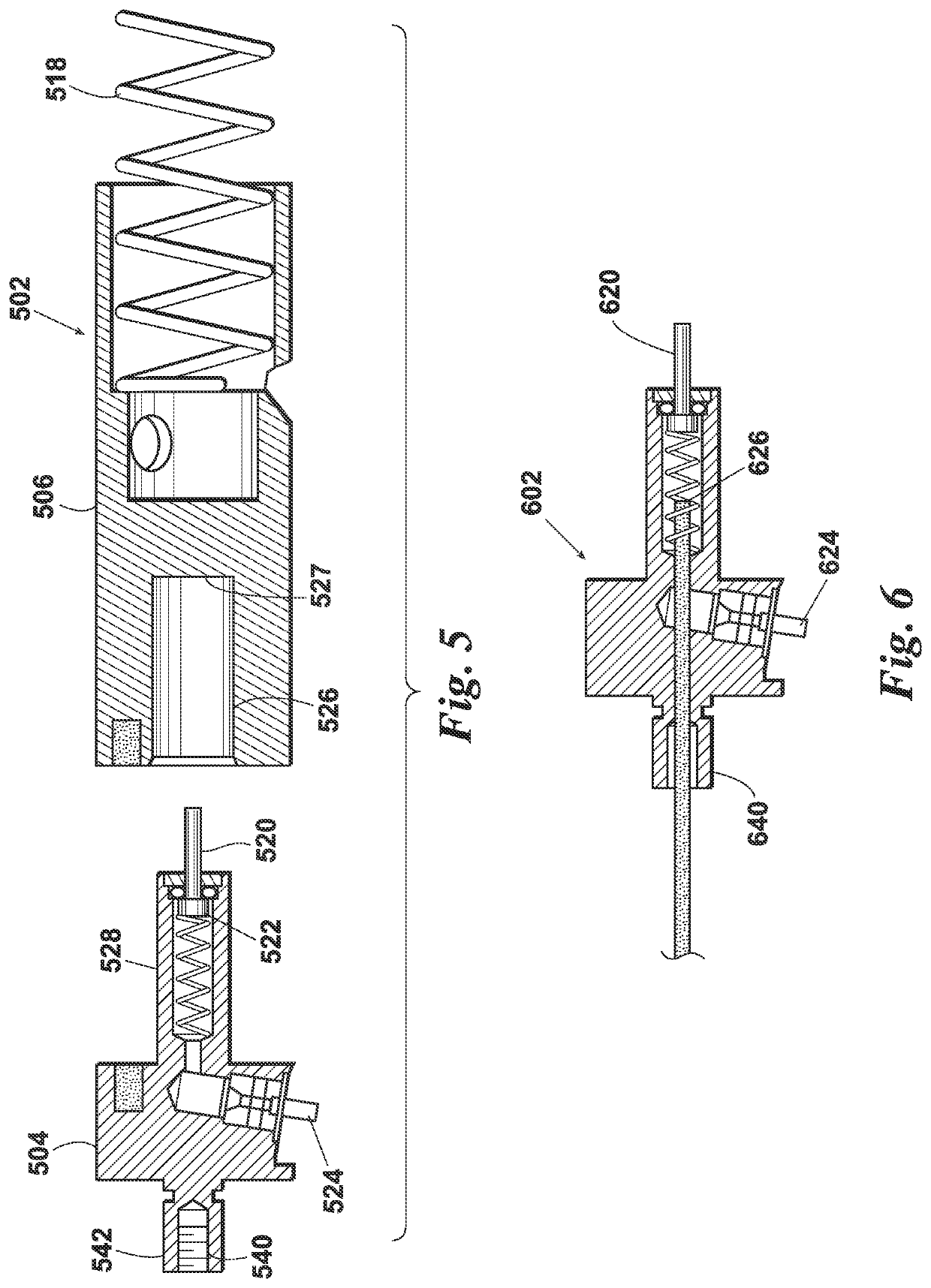
[0031]FIG. 5 is a cut-away exploded side view of an alternate embodiment actuator group 502 including a stationary piston which includes a pin 520 which is a part of valve 522 and actuated by moving bolt 506 to create a firing event as described above.

[0032]In this embodiment, the stationary bolt 506 includes the activator 520. In this embodiment, the metering valve 522 is preferably a poppet valve. Activator 520 releases the pressurized fluid from the reservoir 202 of magazine 200 (or reservoir 302 of magazine 300) to simulate firing of the firearm. This occurs when actuator 520 strikes the back 527 of cavity 526.

[0033]FIG. 6 is a cut-away side...


PUM


Abstract

Pneumatic simulator for an open bolt firearm including an actuator group having a stationary piston and a moving bolt. With each simulated firing cycle producing a firing event, the spring actuates moving bolt toward stationary piston such that the activator unseats a valve located in the stationary piston. Unseating the valve allows regulated compressed gas to exit a high pressure reservoir located in the firearm magazine well which drives the moving bolt back against the spring to complete a firing cycle. Subsequent firing cycles will continue automatically as long as the shooter keeps the trigger depressed. A tension rod, and laser also may comprise the simulator assembly. A nut may be used to secure the tension rod and laser. A laser cable may be used to electrically connect laser to a firing event signal generator. The firing event signal generator may include a magnet located in the moving bolt and a pickup positioned in the stationary piston. With each firing event, the magnet is moved adjacent the pickup which evidences a firing event which generates a signal from the pickup to the laser over the laser cable. The laser then generates a pulse of light which strikes a target to mark a point of impact resulting from the firing event.

Description

CROSS REFERENCE TO RELATED APPLICATION[0001]This application claims the benefit of U.S. Provisional Application No. 62 / 985,457 entitled PNEUMATIC SIMULATOR APPARATUS FOR AN OPEN BOLT AUTOMATIC FIREARM filed Mar. 5, 2020, and U.S. Provisional Application No. 63 / 020,522 entitled PNEUMATIC MACHINE GUN TRAINER CONVERSION filed May 5, 2020, both herein incorporated by reference in their entirety for all purposes.FIELD OF THE INVENTION[0002]This disclosure relates generally to converting an actual firearm to a firearm simulator and more particularly to converting an open bolt automatic firearm to a firearm simulator.BACKGROUND OF THE INVENTION[0003]Firearms have been converted into firearm simulators by replacement of parts of the firearm with simulator parts for simulated shooting such that the resultant firearm comprises a combination of actual firearm components and simulated firearm components. The simulated firearm components have included a simulated barrel unit and a simulated maga...

Claims


Application Information

Patent Timeline
IPC IPC(8): F41A33/06F41A33/02
CPCF41A33/06F41A33/02
Inventor DVORAK, VOJTECH
Owner DVORAK VOJTECH
Learn More