Explosive tube Removal device
- Summary
- Abstract
- Description
- Claims
- Application Information
AI Technical Summary
Benefits of technology
Problems solved by technology
Method used
Image
Examples
Embodiment Construction
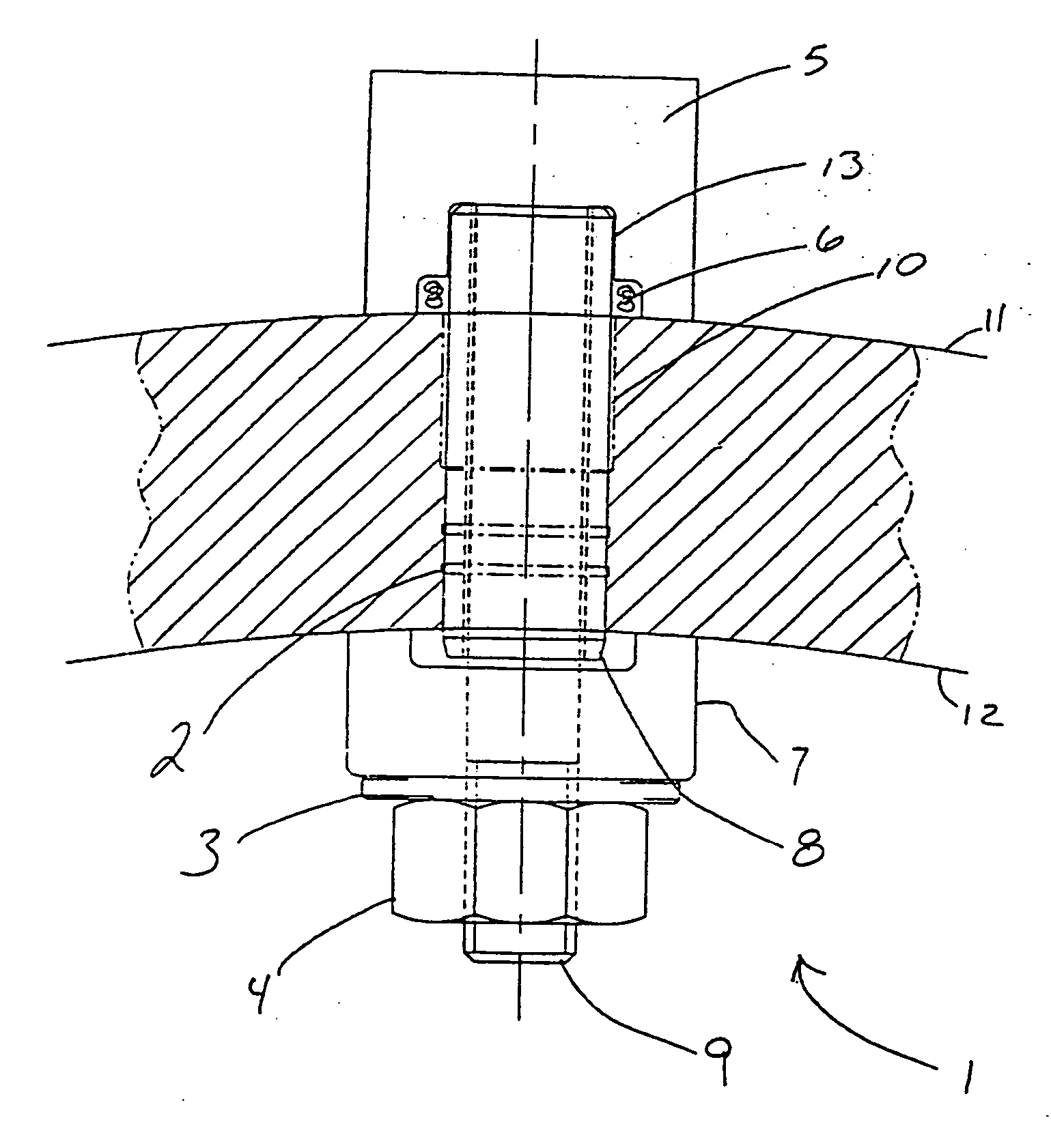
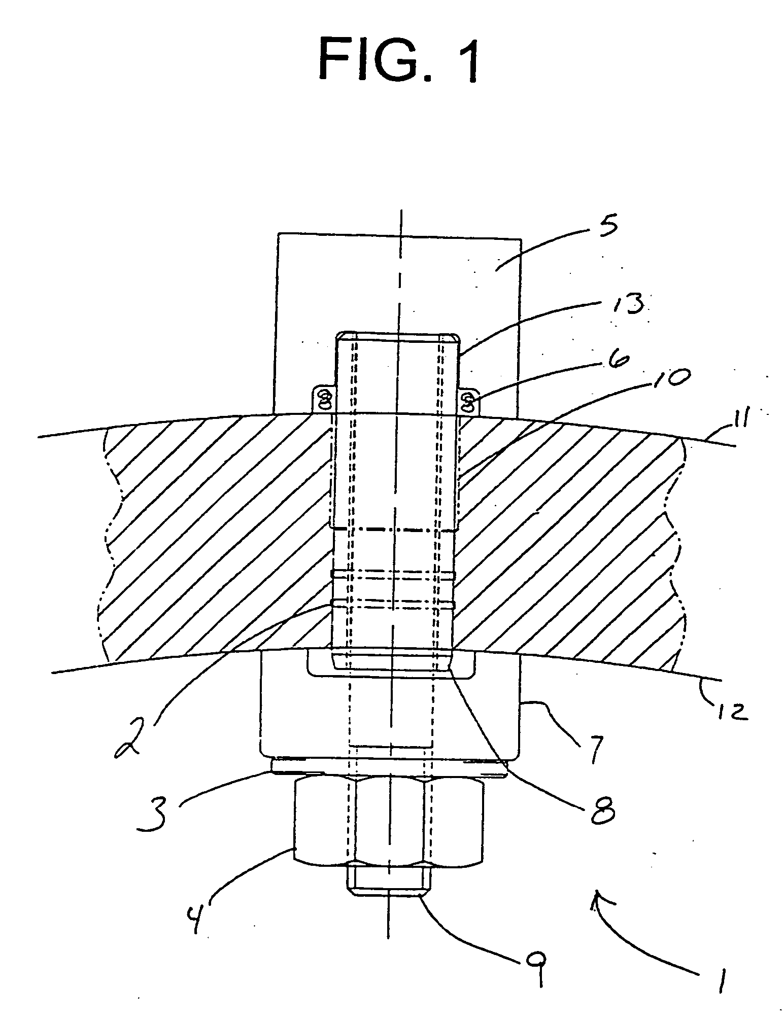
[0019] Referring now to the drawing, in which like reference numerals are used to refer to the same or similar elements, FIG. 1 shows an explosive tube removal device placed over a tube 8 for removing the tube 8 from a hole 10 within about a 4″ metal drum or plate having an outer surface diameter 11 and an inner surface diameter 12. The tube 8 has been expanded into fluid-tight pressure contact within the hole 10. Furthermore, tube 8 has been expanded into ring grooves 2 in the walls of the drum surrounding the hole 10.
[0020] The explosive removal device 1 has a top end that is above the hole 10 and outer surface diameter 11 and a bottom end that is below the hole 10 and inner surface diameter 12.
[0021] The explosive removal device 1 further comprises a cylindrical connecting rod 9 which is inserted within the tube 8 which is expanded within hole 10. The connecting rod 9 is longer than the hole 10 and tube 8 and extends beyond the top and bottom ends of both hole 10 and tube 8.
[0...
PUM
| Property | Measurement | Unit |
|---|---|---|
| Electric charge | aaaaa | aaaaa |
Abstract
Description
Claims
Application Information
 - R&D
- Intellectual Property
- Life Sciences
- Materials
- Tech Scout
- Unparalleled Data Quality
- Higher Quality Content
- 60% Fewer Hallucinations
Browse by: Latest US Patents, China's latest patents, Technical Efficacy Thesaurus, Application Domain, Technology Topic, Popular Technical Reports.
© 2025 PatSnap. All rights reserved.Legal|Privacy policy|Modern Slavery Act Transparency Statement|Sitemap|About US| Contact US: help@patsnap.com


