Three-dimensional heat dissipating device

Pending Publication Date: 2022-01-20
AURAS TECH
View PDF3 Cites 0 Cited by
  • Summary
  • Abstract
  • Description
  • Claims
  • Application Information

AI Technical Summary

Benefits of technology

The invention described in this patent allows for a three-dimensional heat dissipating device that increases the space for heat dissipation and improves the efficiency of the vaporized working fluid by accelerating its recirculation.

Problems solved by technology

Therefore, the heat dissipation efficiency must be improved, otherwise a problem of excessive system temperature will appear immediately.
However, the heat dissipation efficiency of the vapor chamber is still insufficient, and structural improvement and refinement are required to increase, so as to improve the heat dissipation space and the reflux effect of the vaporized working fluid, thereby improving the thermal cycle efficiency.

Method used


Image

  • Three-dimensional heat dissipating device
  • Three-dimensional heat dissipating device
  • Three-dimensional heat dissipating device

Examples


Embodiment Construction

[0037]Reference will now be made in detail to the present embodiments of the disclosure, examples of which are illustrated in the accompanying drawings. Wherever possible, the same reference numbers are used in the drawings and the description to refer to the same or like parts. According to the embodiments, it will be apparent to those skilled in the art that various modifications and variations can be made to the structure of the disclosure without departing from the scope or spirit of the disclosure.

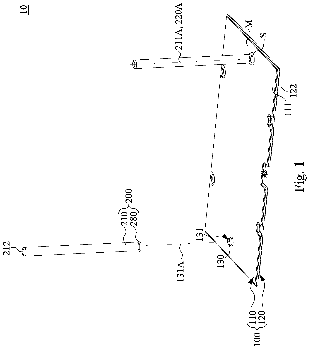
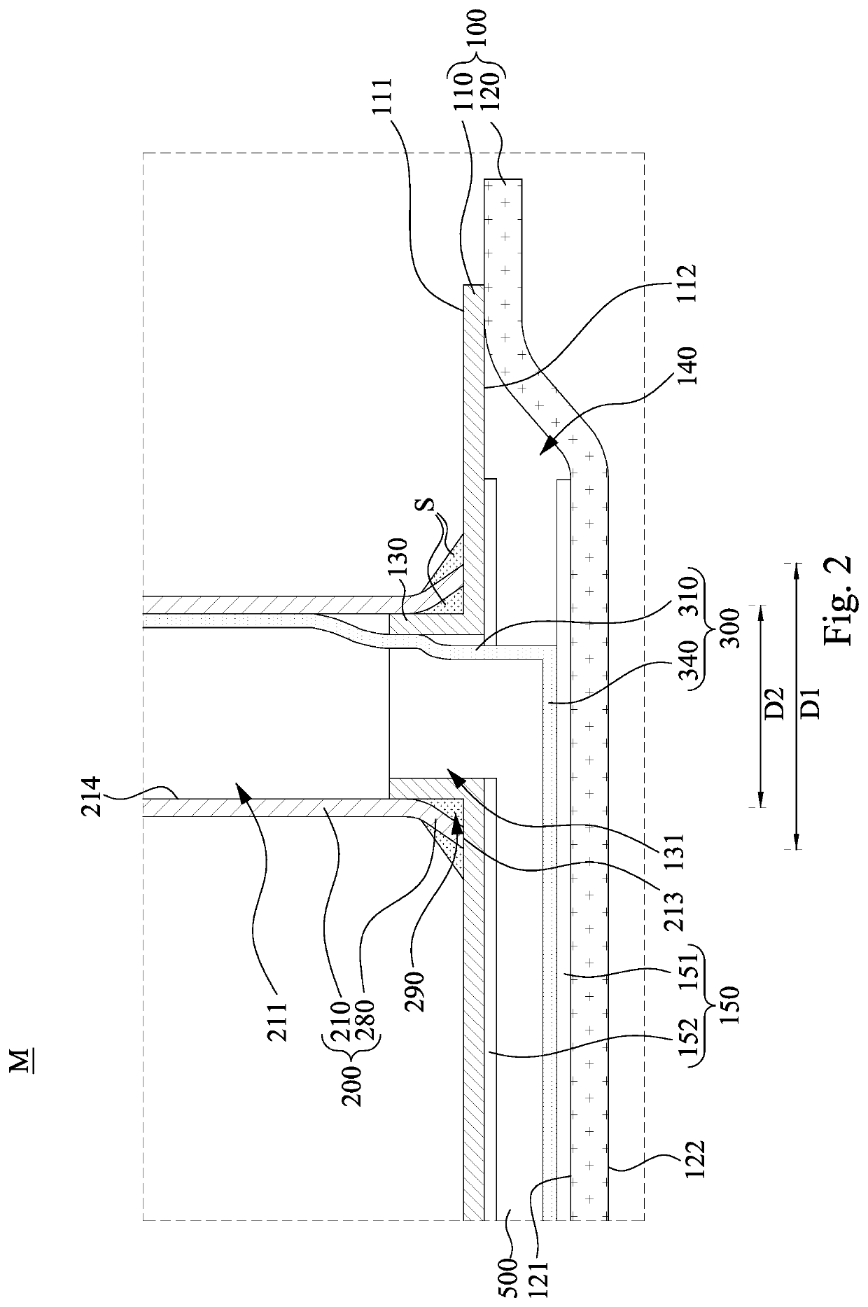
[0038]Reference is now made to FIG. 1 to FIG. 2, in which FIG. 1 is a partially exploded view of a three-dimensional heat dissipating device 10 according to one embodiment of the disclosure, and FIG. 2 is a partial cross section view of an area M of the three-dimensional heat dissipating device 10 of FIG. 1. As shown in FIG. 1 and FIG. 2, the three-dimensional heat dissipating device includes a vapor chamber 100, a plurality (e.g., two) of heat pipes 200 and a working fluid 500. The v...


PUM


Abstract

A three-dimensional heat dissipating device includes a vapor chamber, a heat pipe and a working fluid. The vapor chamber includes an inner cavity, a first capillary structure disposed within the inner cavity, and a first joint connected with the inner cavity. The heat pipe includes a pipe body, a second capillary structure, and a second joint disposed at the pipe body and connected to the first joint, such that a pipe space of the pipe body is in communication with the inner cavity. The second capillary structure includes a first section and a second section. The first section is fixedly disposed within a pipe space and connected to the second section. The second section is curvedly extended from one end of the first section, and connected to the first capillary structure. The working fluid is filled within the pipe space and the inner cavity.

Description

RELATED APPLICATIONS[0001]This application claims priority to U.S. Application Ser. No. 63 / 053,953, filed Jul. 20, 2020, which is herein incorporated by reference.BACKGROUNDField of Disclosure[0002]The disclosure relates to a heat dissipating device. More particularly, the disclosure relates to a three-dimensional heat dissipating device.Description of Related Art[0003]With highly development of semiconductor technology, the speed of a working chip will be getting faster, and the heat generated by the working chip is getting higher. Therefore, the heat dissipation efficiency must be improved, otherwise a problem of excessive system temperature will appear immediately.[0004]For example, since a vapor chamber is provided with characteristics of thermal conduction, light weight and simple structure etc., a conventional manner is to configure a vapor chamber on an electronic component. In order to send the vaporized working fluid back to an evaporation area in the vapor chamber, a capil...

Claims


Application Information

Patent Timeline
IPC IPC(8): F28D15/04F28D15/02F28F1/32
CPCF28D15/046F28D15/0233F28F2215/04F28F1/32F28D15/0275F28D15/04F28F1/12F28F3/02F28F9/26F28D15/0283H05K7/2039F28F2215/08F28F2230/00
Inventor CHEN, CHIH-WEICHANG, TIEN-YAOKUO, CHE-WEICHUANG, HSIANG-CHIHHUANG, JYUN-WEICHANG, CHENG-JU
Owner AURAS TECH
Why Eureka
Try Eureka