Brake pad state estimation device and brake pad state estimation method

a technology of estimation device and state estimation method, which is applied in the direction of braking system, braking components, friction lining, etc., can solve the problems of consuming a considerable amount of computational resources, the process of continuously calculating the state of the brake pad based on the detection information of the sensor, and the wear characteristics of the brake pad, so as to achieve efficient and reliable estimation of the state of the brake pad without consuming resources more than necessary.

Pending Publication Date: 2022-01-20
TOYOTA JIDOSHA KK
View PDF7 Cites 1 Cited by
  • Summary
  • Abstract
  • Description
  • Claims
  • Application Information

AI Technical Summary

Benefits of technology

[0009]An object of the present disclosure is to provide a technique that can suppress unnecessary consumption of at least one of a computational resource, a storage resource, and a communication resource, when estimating a brake pad state including at least one of a wear volume and a temperature of a brake pad of a vehicle.
[0026]That is, the processing frequency is set to be low in a case where an impact on the brake performance is low, and the processing frequency is set to be high in a case where the impact on the brake performance is high. It is thus possible to suppress the resource consumption in the case where the impact on the brake performance is low, and to calculate the brake pad state more precisely in the case where the impact on the brake performance is high. In other words, it is possible to efficiently secure an estimation accuracy of the brake pad state without consuming resources more than necessary.

Problems solved by technology

Moreover, wear characteristics of the brake pad also depend on a temperature of a contact surface (friction part) that comes in contact with the brake rotor.
In general, a sampling period of the sensor signal is very short and thus the amount of sensor detection information becomes enormous.
Accordingly, the process of continuously calculating the brake pad state based on the sensor detection information is likely to consume a considerable amount of computational resources.
Moreover, a process of continuously storing a result of calculation of the brake pad state in a storage device is likely to consume a considerable amount of storage resources.
Furthermore, a process of continuously transmitting the result of calculation of the brake pad state to the outside is likely to consume a considerable amount of communication resources.

Method used


Image

  • Brake pad state estimation device and brake pad state estimation method
  • Brake pad state estimation device and brake pad state estimation method
  • Brake pad state estimation device and brake pad state estimation method

Examples


Embodiment Construction

[0036]Embodiments of the present disclosure will be described below with reference to the attached drawings.

1. Outline

1-1. Vehicle and Braking Device

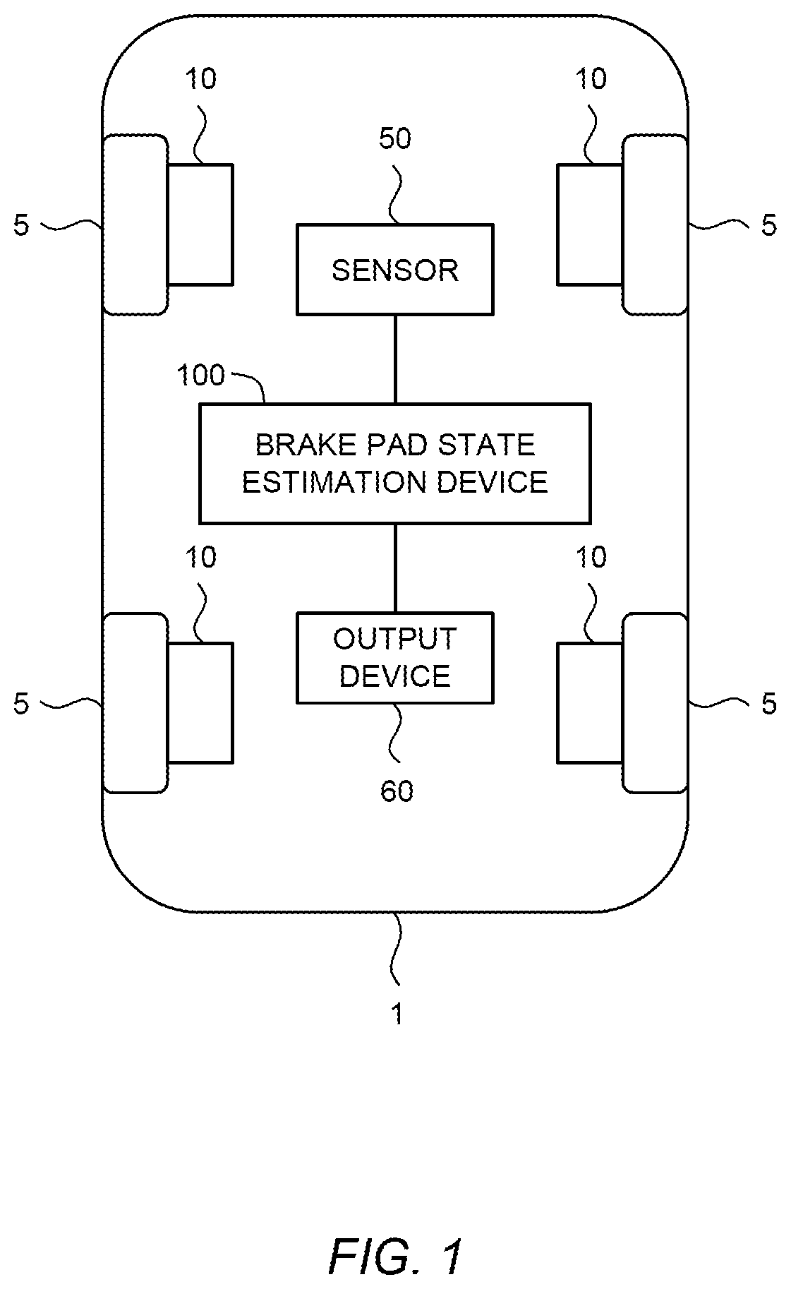
[0037]FIG. 1 is a schematic diagram showing a configuration of a vehicle 1 according to the present embodiment. The vehicle 1 may be an automated driving vehicle controlled by an automated driving system. The vehicle 1 includes a wheel (tire) 5 and a braking device 10. The braking device 10 generates a braking force in response to a brake operation by a driver or the automated driving system.

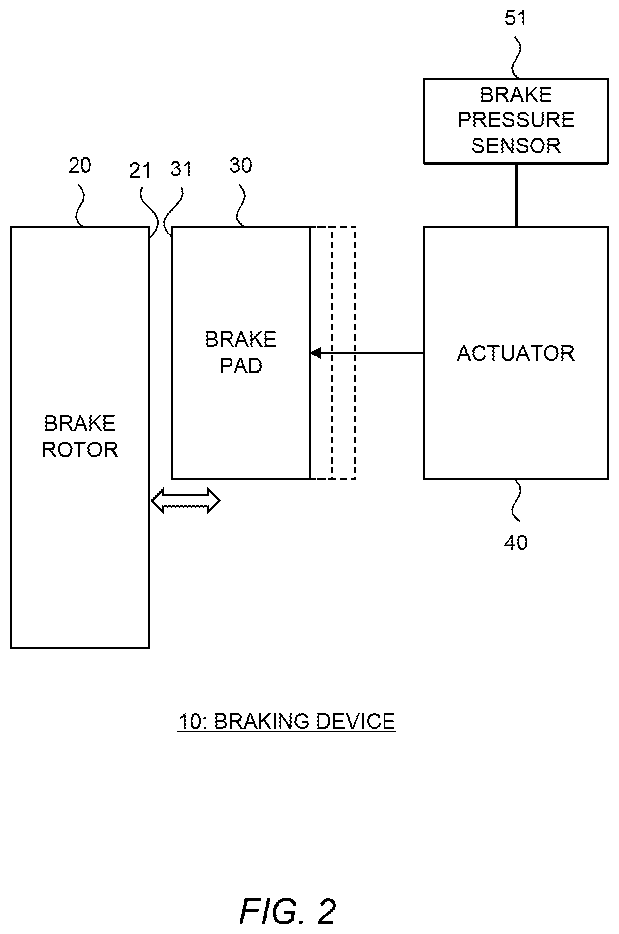
[0038]FIG. 2 is a block diagram schematically showing a configuration of the braking device 10 according to the present embodiment. The braking device 10 includes a brake rotor 20, a brake pad 30, and an actuator 40.

[0039]The brake rotor 20 is a rotatable member that rotates with the wheel 5. For example, a material of the brake rotor 20 is cast iron. The brake pad 30 is a friction material that comes in contact with the brake rotor 20. For example,...


PUM


Abstract

A brake pad state estimation device estimates a brake pad state including at least one of a wear volume and a temperature of a brake pad of a vehicle. The brake pad state estimation device performs: a brake pad state calculation process calculating the brake pad state based on sensor detection information during braking; and an information output process storing the brake pad state information in a storage and / or transmitting the brake pad state information to the outside. The brake pad state estimation device variably sets a processing frequency of at least one of the brake pad state calculation process and the information output process. The processing frequency when a vehicle speed is lower is lower than the processing frequency when the vehicle speed is higher, or the processing frequency when a brake pressure is lower is lower than the processing frequency when the brake pressure is higher.

Description

CROSS-REFERENCE TO RELATED APPLICATION[0001]The present disclosure claims priority under 35 U.S.C. § 119 to Japanese Patent Application No. 2020-123173, filed Jul. 17, 2020, the contents of which application are incorporated herein by reference in their entirety.BACKGROUNDTechnical Field[0002]The present disclosure relates to a technique of estimating a brake pad state including at least one of a wear volume and a temperature of a brake pad of a vehicle.Background Art[0003]Japanese Patent No. 6207075 discloses a wear volume computation device that calculates a wear volume of a braking member of a railroad car and the like. The wear volume computation device calculates (estimates) the wear volume of the braking member based on a brake pressure, a speed of a braking target, and a braking time.[0004]Japanese Laid-Open Patent Application Publication No. 2005-067508 discloses a wear alert system. The wear alert system estimates a wear volume of a brake pad by using an on-board sensor, an...

Claims


Application Information

Patent Timeline
Patent Type & Authority Applications(United States)
IPC IPC(8): F16D66/02B60T17/22F16D66/00
CPCF16D66/021B60T17/221F16D66/00F16D2066/006B60T2270/88F16D2066/001B60T2250/04F16D66/022F16D69/04F16D66/026F16D2066/005
Inventor MATSUI, NORIYOSHI
Owner TOYOTA JIDOSHA KK
Why Eureka
Try Eureka