Power-over-fiber system and method for operating a power-over-fiber system

a technology of power-over-fiber and fiber, applied in the direction of fiber transmission, electromagnetic transmission, electrical apparatus, etc., can solve the problems of reducing the electrical output power of the system, not enough energy is supplied to the device, and the sensor does not provide any information about the output power of the electromagnetic energy receiver, so as to achieve efficient compensation of the reduction of the performance of the optical sink

Active Publication Date: 2021-12-30
ROHDE & SCHWARZ GMBH & CO KG
View PDF13 Cites 0 Cited by
  • Summary
  • Abstract
  • Description
  • Claims
  • Application Information

AI Technical Summary

Benefits of technology

[0048]controlling the optical source to change, in particular enhance, an optical power of the optical signal.
[0049]This achieves the advantage that a reduced performance of the optical sink can efficiently be compensated.

Problems solved by technology

However, over time, the electrical output power of the system can be reduced, e.g. due to a deterioration of the conversion element over time or due to temperature effects, so that at some point not enough energy is supplied to the device.
However, this sensor does not provide any information about the output power of the electromagnetic energy receiver.
However, this equipment cannot detect a deterioration of the light conversion to electrical energy.
If not enough electrical energy is supplied by such a PoF system, the operation of the device powered by the PoF system may be interrupted or disturbed.
However, this leads to additional costs and complexity.

Method used


Image

  • Power-over-fiber system and method for operating a power-over-fiber system
  • Power-over-fiber system and method for operating a power-over-fiber system
  • Power-over-fiber system and method for operating a power-over-fiber system

Examples


Embodiment Construction

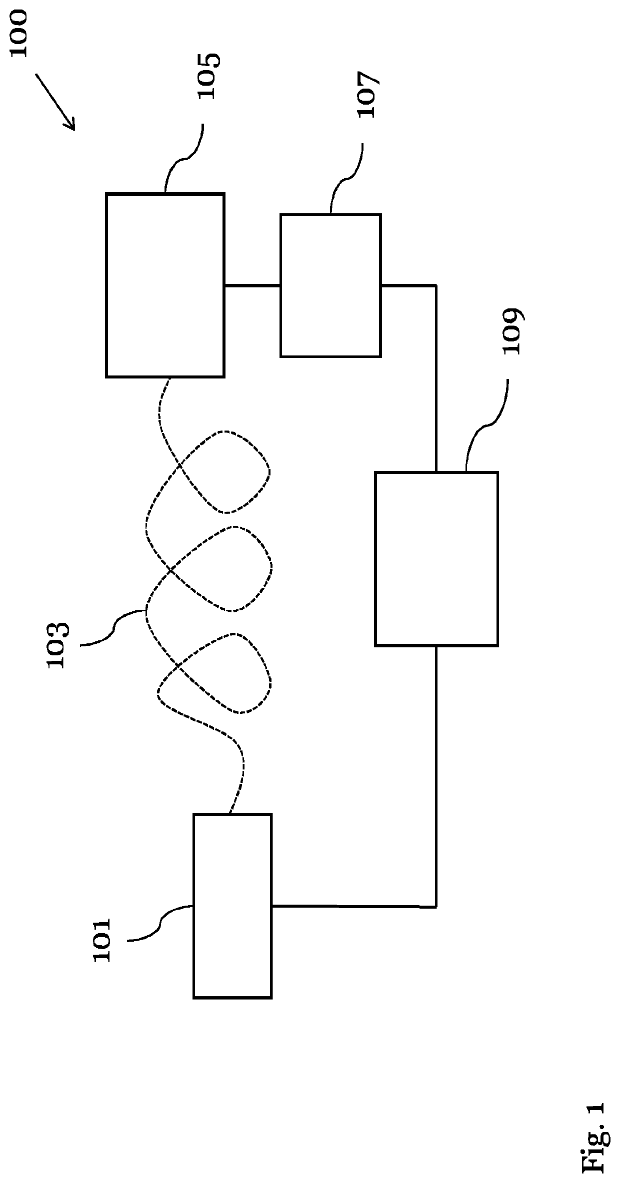
[0057]FIG. 1 shows a schematic diagram of a power-over-fiber (PoF) system 100 according to an embodiment.

[0058]The POF system 100 comprises an optical source 101 configured to generate an optical signal, wherein the optical signal comprises an intensity modulation, an optical fiber 103 configured to receive the optical signal from the optical source 101 and to guide the optical signal, and an optical sink 105, which is configured to receive the optical signal from the optical fiber 103 and to convert the optical signal into an electrical signal.

[0059]The POF system 100 in FIG. 1 further comprises a detection unit 107, which is configured to detect at least one characteristic of the electrical signal, wherein the characteristic is at least partially caused by the intensity modulation of the optical signal, and a control unit 109, which is configured to control the optical source 101 based on the detected characteristic.

[0060]The optical source 101 can be a laser or can comprise a las...


PUM

PropertyMeasurementUnit
opticalaaaaaaaaaa
electricalaaaaaaaaaa
internal resistanceaaaaaaaaaa

Abstract

The invention relates to a power-over-fiber (PoF) system, comprising: an optical source configured to generate an optical signal, wherein the optical signal comprises an intensity modulation; an optical fiber configured to receive the optical signal from the optical source and to guide the optical signal; an optical sink, which is configured to receive the optical signal from the optical fiber and to convert the optical signal into an electrical signal; a detection unit, which is configured to detect at least one characteristic of the electrical signal, wherein the characteristic is at least partially caused by the intensity modulation of the optical signal; and a control unit, which is configured to control the optical source based on the detected characteristic.

Description

TECHNICAL FIELD OF THE INVENTION[0001]The invention relates to the technical field of energy supply systems. In particular, the invention relates to a power-over-fiber (PoF) system, a method for operating a PoF system, a measurement device comprising such a PoF system as well as the use of such a PoF system in a measurement device.BACKGROUND OF THE INVENTION[0002]A Power-over-fiber (PoF) system uses optical power transmitted in an optic fiber cable as an energy source. Such a systems allows remotely powering a device, while electrically isolating the device from a power supply. For instance, a PoF system can be used to power components of a measurement device, which are electrically isolated from the rest of the device to avoid electrical interferences or disturbances.[0003]Generally, a PoF system relies on a conversion of the optical power into electrical power via a conversion element of the system. The electrical power can then be supplied to the powered device. However, over tim...

Claims


Application Information

Patent Timeline
Patent Type & Authority Applications(United States)
IPC IPC(8): H04B10/25H04B10/54H04B10/69H04B10/67
CPCH04B10/25H04B10/672H04B10/69H04B10/541H04B10/807H04B10/806H04B10/808H02J50/30H04B10/504H04B10/516
Inventor KRIMMER, ROLANDZIEGLER, ANDREAS
Owner ROHDE & SCHWARZ GMBH & CO KG
Why Eureka
Try Eureka