
Composite display screen, composite display screen module, and display control method thereof

a display screen and composite technology, applied in the field of display technologies, can solve the problems of certain loss of screen ratio, inability to adjust the screen ratio, and use of free-form cutting methods, so as to improve the transmittance and transparency, improve the visual experience of users, and improve the effect of screen ratio

Inactive Publication Date: 2021-12-30
WUHAN CHINA STAR OPTOELECTRONICS TECH CO LTD
View PDF0 Cites 2 Cited by
  • Summary
  • Abstract
  • Description
  • Claims
  • Application Information

AI Technical Summary

Benefits of technology

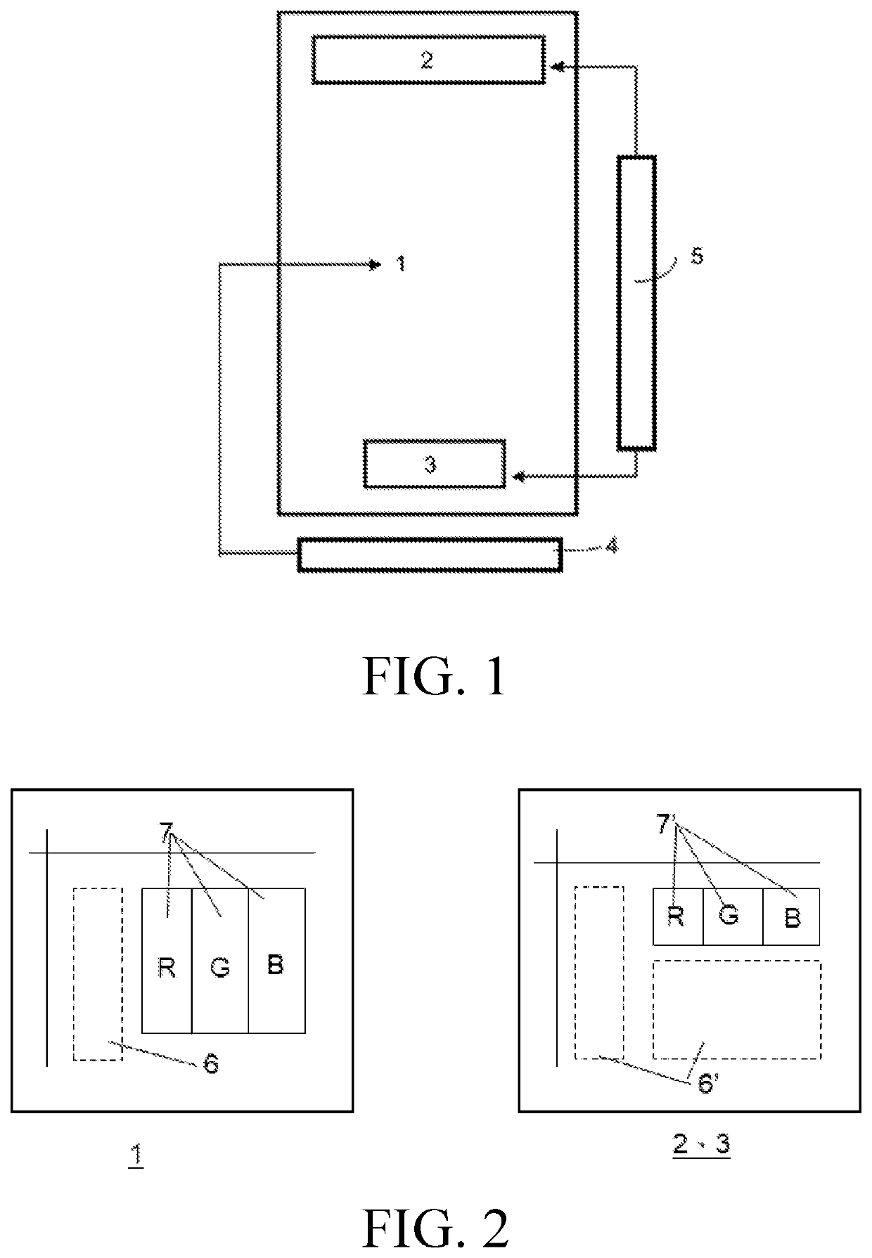
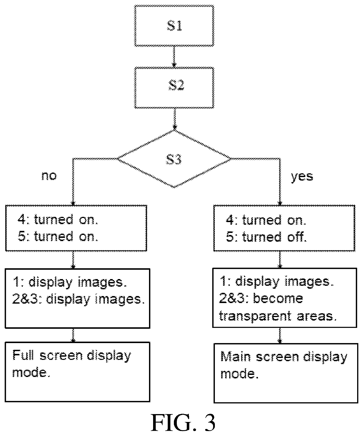
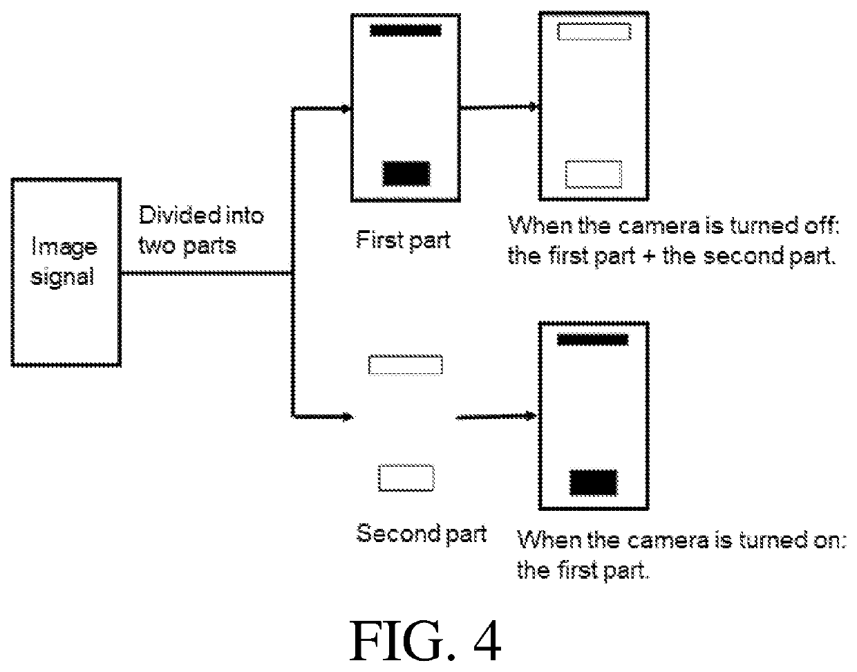
The present patent discloses a composite display screen and a control method for displaying images on the main display screen and a sub-display screen. By controlling the main display driver circuit and the sub-driver circuit, the screens can show different types of information. This allows for a full screen display and improves the overall screen ratio for better user experience. The sub-display screen has a greater transparent area, which improves its function and ensures the components work properly.

Problems solved by technology

With full screens becoming more popular, how to increase the screen ratio becomes an important problem.
Although the screen ratio has been greatly improved by a free-form cut screen, devices on a motherboard of a mobile phone, such as cameras, still cannot be avoided, thereby causing a certain loss of the screen ratio.
Technical problem: a free-form cutting method is used to process panels in current technology to avoid cameras, infrared holes, and fingerprint areas.
Although the screen ratio has been greatly improved by a free-form cut screen, devices on a motherboard of a mobile phone, such as cameras, still cannot be avoided, thereby causing a certain loss of the screen ratio.

Method used


Image

  • Composite display screen, composite display screen module, and display control method thereof
  • Composite display screen, composite display screen module, and display control method thereof
  • Composite display screen, composite display screen module, and display control method thereof

Examples


Embodiment Construction

[0031]In order to make the above and other objects, features, and advantages of the present disclosure more comprehensible, the following describes preferred embodiments of the present disclosure and the accompanying drawings for detailed descriptions. In the description of the present disclosure, it should be understood that terms such as “upper”, “lower”, “front”, “rear”, “left”, “right”, as well as derivative thereof should be construed to refer to the orientation as described or as shown in the drawings under discussion. These relative terms are for convenience of description, do not require that the present disclosure be constructed or operated in a particular orientation, and shall not be construed as causing limitations to the present disclosure. The identical or similar reference numerals constantly denote the identical or similar elements or elements having the identical or similar functions in the drawings.

[0032]A composite display screen provided by the present disclosure...


PUM


Abstract

A composite display screen, a composite display screen module, and a display control method thereof are provided. The composite display screen includes a main display screen corresponding to a main display area and electrically connected to a first display driver integrated circuit; and at least one sub-display screen corresponding to a sub-display area and electrically connected to a second display driver integrated circuit, wherein the sub-display area is disposed on an upper part or / and a lower part of the composite display screen, and a plurality of functional components are disposed correspondingly in the sub-display area. A first pixel unit in the main display area includes a first sub-pixel unit and a first transparent subunit, a second pixel unit of the sub-display screen comprises a second sub-pixel unit and a second transparent subunit, and an area of the second transparent subunit is greater than an area of the first transparent subunit.

Description

FIELD OF INVENTION[0001]The present disclosure relates to the field of display technologies, and more particularly, to a composite display screen, a composite display screen module, and a display control method thereof.BACKGROUND OF INVENTION[0002]As the new generation of display technologies, organic light-emitting diodes (OLEDs) have wider color gamut and faster response times. They can also be made lighter and thinner in terms of thicknesses. With full screens becoming more popular, how to increase the screen ratio becomes an important problem. A free-form cutting method is used to process panels in current technology to avoid cameras, infrared holes, and fingerprint areas. Although the screen ratio has been greatly improved by a free-form cut screen, devices on a motherboard of a mobile phone, such as cameras, still cannot be avoided, thereby causing a certain loss of the screen ratio.[0003]Therefore, how to improve the screen ratio and to achieve a full screen display is the pr...

Claims


Application Information

Patent Timeline
Patent Type & Authority Applications(United States)
IPC IPC(8): G06F3/14G09G3/20G09G5/377
CPCG06F3/1431G09G3/20G09G2370/22G09G2340/12G09G5/377G09F9/302G09G5/14G09G3/3208G09G2310/0221G09G2300/026G09G2360/144
Inventor LI, RENPENGLIU, FENG
Owner WUHAN CHINA STAR OPTOELECTRONICS TECH CO LTD
Learn More