
Ionizers having carbon nanotube ion emitting heads

a technology of carbon nanotube and ionizer, which is applied in the field of battery-operated portable ion generators and ionizers, can solve the problems of affecting the ion generating performance of carbon fiber emitters, affecting the ability of ion generating, and reducing so as to improve increase the surface area , the effect of increasing the yield of ion

Pending Publication Date: 2021-12-23
HEADWATERS INCORPORATED
View PDF0 Cites 0 Cited by
  • Summary
  • Abstract
  • Description
  • Claims
  • Application Information

AI Technical Summary

Benefits of technology

The present invention provides a method for improving the yield of ion emission from carbon nanotube ion emitting heads. This is achieved by applying a coat of a preselected chemical, such as a solution of nitric acid, to the carbon nanotube ion emitter. This method increases surface area and enhances ion emission.

Problems solved by technology

The technical problem addressed in this patent is how to create an efficient and durable ionizer that can effectively control the amount of ions released without causing damage to the surrounding environment through excessive ozone production. Current technology uses carbon fiber brushes, which are susceptible to breaking and wearing down over time due to environmental conditions and their design limitations. This leads to decreased efficiency and increased maintenance costs.

Method used


Image

  • Ionizers having carbon nanotube ion emitting heads
  • Ionizers having carbon nanotube ion emitting heads
  • Ionizers having carbon nanotube ion emitting heads

Examples


Embodiment Construction

[0027]It is to be understood that the invention is not limited in its application to the details of construction or to the arrangements of the components set forth in the following description or illustrated in the drawings. The invention is capable of other embodiments of being practiced and carried out in various ways. Also, it is to be understood that the phraseology and terminology employed herein are for the purpose of the description and should not be regarded as limiting.

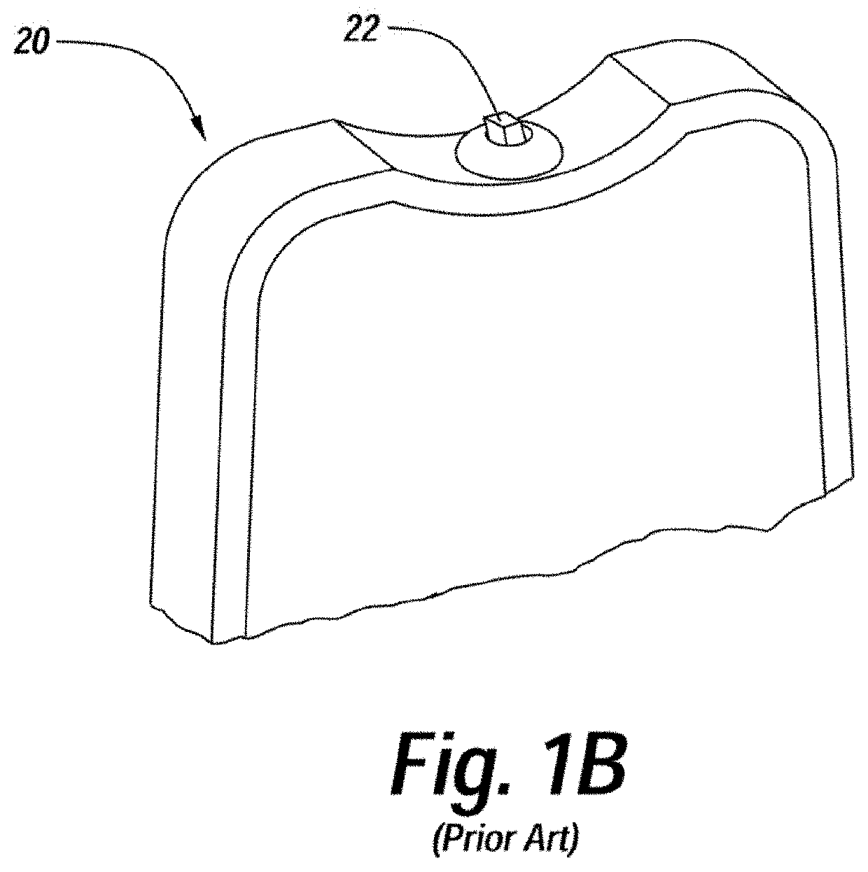
[0028]Turning now descriptively to the drawings, FIG. 1A illustrates generally at 10 a prior art portable, rechargeable, personal ionic air purifier. The user hangs the purifier 10 around their neck using the conductive cord or lanyard 12 and turns it “on” using the switch 14. A cloud of ions, not shown, is thereby produced off of carbon fiber brush ion emitter 16 towards the facial area, not shown, to energize the personal airspace with ions and remove particulates therefrom. These ions attract opposite char...


PUM


Abstract

Ionizers having carbon nanotube (CNT) ion emitting heads of the present invention include ionization circuitry supplying voltage at ionization potential and carbon nanotube (CNT) ion emitters operatively connected thereto. The carbon nanotube (CNT) ion emitters are mechanically and electrically stable, provide good ion flows for air purification and/or air invigoration when actuated at ionization potential and are capable of prolonged use in highly polluted environments.

Description


Claims


Application Information

Patent Timeline
Owner HEADWATERS INCORPORATED
Learn More