
Supporting mechanism and supporting device having the same

a technology of supporting mechanism and supporting device, which is applied in the direction of machine supports, mechanical devices, stands/trestles, etc., can solve the problems of deterioration of the durability of the swivel torque hinge, aging variations of friction torque, and equipment stopping state or sliding force, etc., to reduce the offset load

Active Publication Date: 2021-12-16
KEM HONGKONG
View PDF3 Cites 0 Cited by
  • Summary
  • Abstract
  • Description
  • Claims
  • Application Information

AI Technical Summary

Benefits of technology

This invention provides a better supporting mechanism for a swivel torque hinge. The hinge shaft is pivotally supported on a supporting arm, and a bracket is attached to the hinge shaft. A fixing guide member is rotatably attached to the bracket and the supporting arm. This mechanism reduces the load on the friction torque generating mechanism, improving its durability. Moreover, when shaft bearing members are attached to the supporting arm and the fixing guide member, the rotation movement of the supporting arms becomes smoother.

Problems solved by technology

In a supporting device for a supported device such as a display for monitor, as is disclosed in JP Laid-Open Patent Application No. 2005-83538, a problem lies in that a load applied to a friction torque generating mechanism of a swivel torque hinge being a supporting mechanism via a supporting arm shifts toward one side (i.e. a section around a display device for the monitor), which makes a rotational torque unstable to cause variations in a stopping state or sliding force of equipment.
Furthermore, there is another problem that an offset load applied to axial urging members such as spring washers provided on a swivel torque hinge may cause aging variations in friction torque of the above-mentioned friction torque generating mechanism, as well as a deterioration in durability of the swivel torque hinge.

Method used


Image

  • Supporting mechanism and supporting device having the same
  • Supporting mechanism and supporting device having the same
  • Supporting mechanism and supporting device having the same

Examples


Embodiment Construction

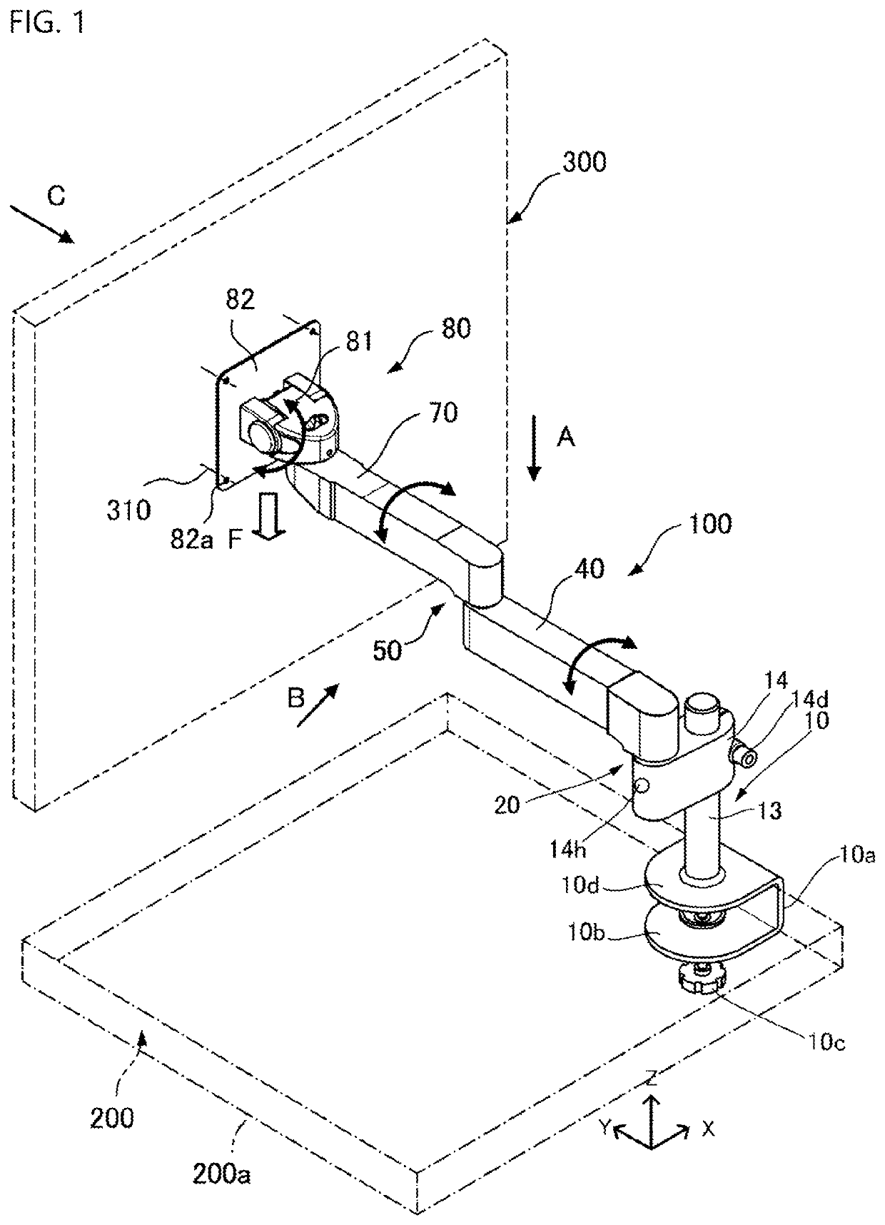
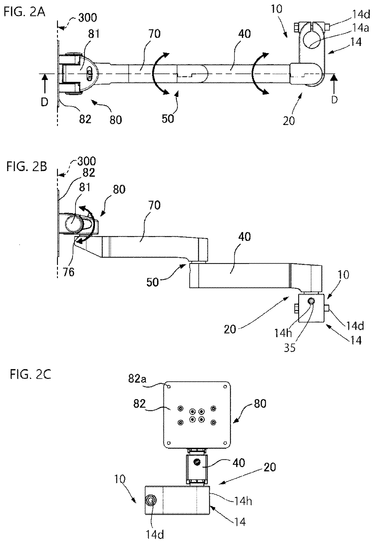
[0029]In the following, reference is made to a supporting device 100, as well as to supporting mechanisms 20, 50 used for the supporting device 100, with reference to the drawings. It is noted that the following description is based on x-, y- and z-axes as shown in FIG. 1 to define a direction within an xy plane as a horizontal, a direction of an arrow along z-axis as upward, and that of an arrow along y-axis as forward. Further in the drawings, rotatable directions are shown using two-way arrows as are necessary.

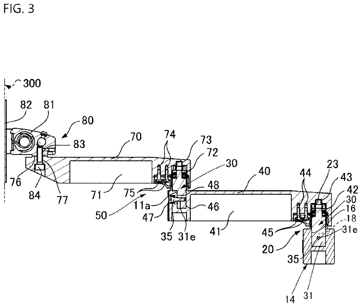
[0030]First, as shown in FIGS. 1 and 3, a supporting device 100 comprises a lifting device 10 being an example of attaching mechanism a top plate 200 a of a desk 200 being an example of attaching element, a first supporting arm 40 attached to an attaching member 14 of the lifting device 10 via a first supporting mechanism 20, such that its one end portion is swingable in a horizontal direction, a second supporting arm 70 attached to the other end portion of the first suppor...


PUM


Abstract

A supporting mechanism for a supporting device that supports supporting arms to which a pressing down load is applied on one side relative to an attaching element such that the former are mobile at least in a horizontal direction, as well as a supporting device having a supporting mechanism is disclosed. The solution is sought by using a swivel torque hinge having a friction torque generating mechanism using elastic members such as friction washers and spring washers for the supporting mechanism by pivotally supporting a shaft upper portion of a hinge shaft of the swivel torque hinge on an attaching hole portion provided on the supporting arms by providing a bracket supporting the supporting arms on the hinge shaft via the friction torque generating mechanism.

Description

FIELD OF THE INVENTION[0001]The invention relates to a supporting mechanism suitable in use for a supporting device which supports a supported device such as a display for monitor, such that the former is mobile relative to an attaching element such as an attaching base in horizontal, longitudinal and vertical directions; the invention also relates to a supporting device having the supporting mechanism.BACKGROUND ART[0002]JP Laid-Open Patent Application No. 2005-83538 discloses a supporting mechanism for a supporting device which uses supporting arms to hold various kinds of equipment such as a display for monitor and office equipment relative to an attaching base such as work desk and to support the above-mentioned equipment such that the former is mobile in horizontal, longitudinal and vertical directions.[0003]In the supporting mechanism for a supporting device of the equipment disclosed in JP Laid-Open Patent Application No. 2005-83538, a section around the attaching base is cou...

Claims


Application Information

Patent Timeline
Patent Type & Authority Applications(United States)
IPC IPC(8): F16M13/02F16M11/08
CPCF16M13/022F16M11/08F16M11/121F16M11/10F16M13/02F16M11/2014F16M2200/022F16M2200/027F16M11/24
Inventor MIURA, FUMIAKI
Owner KEM HONGKONG
Learn More