
Hybrid vehicle

a hybrid vehicle and vehicle body technology, applied in the field of hybrid vehicles, can solve the problems of difficult to completely prevent, driver's strange or uncomfortable feeling, and so as to reduce the feeling of strangeness, the durability of the frictional engagement elements may be adversely influenced, and the amount of heat generated in the frictional engagement elements may be increased.

Active Publication Date: 2018-01-30
TOYOTA JIDOSHA KK
View PDF3 Cites 0 Cited by
  • Summary
  • Abstract
  • Description
  • Claims
  • Application Information

AI Technical Summary

Benefits of technology

This patent aims to reduce the discomfort felt by drivers during gear shifts in mechanical stepwise variable transmissions. The inventors have considered how to improve the fuel efficiency of automatic shifts while also maintaining high driving performance. They found that by making the virtual gear positions assigned to each mechanical gear position when selecting the gear position the same for both upshifts and downshifts, a higher fuel economy performance can be obtained. On the other hand, in the manual shift mode, where the driver frequently selects gear positions, it is important to prevent excessive heat generation and maintain the durability of the frictional engagement elements. This is achieved by making the virtual gear positions different for each direction of gear selection. Overall, this patent provides a solution for improving the driving experience and performance of automatic and manual sh releases in vehicles with mechanical stepwise variable transmissions.

Problems solved by technology

However, it is difficult to completely prevent shift shock during shifting of the mechanical stepwise variable transmission, even under the shift control disclosed in JP 2006-321392 A, and even a slight shock due to a shift of the mechanical stepwise variable transmission may cause the driver to feel strange or uncomfortable, since the rotational speed of the drive source is substantially constant.
As a result, the durability of the frictional engagement elements may be adversely influenced.
In this case, however, upshift and downshift of the virtual gear position are unlikely to be repeated in a short time.

Method used


Image

  • Hybrid vehicle
  • Hybrid vehicle
  • Hybrid vehicle

Examples


Embodiment Construction

[0037]Some embodiments of the disclosure will be described with reference to the drawings. In the embodiments, the disclosure is applied to a hybrid vehicle of an FR (front-engine, rear-drive) type.

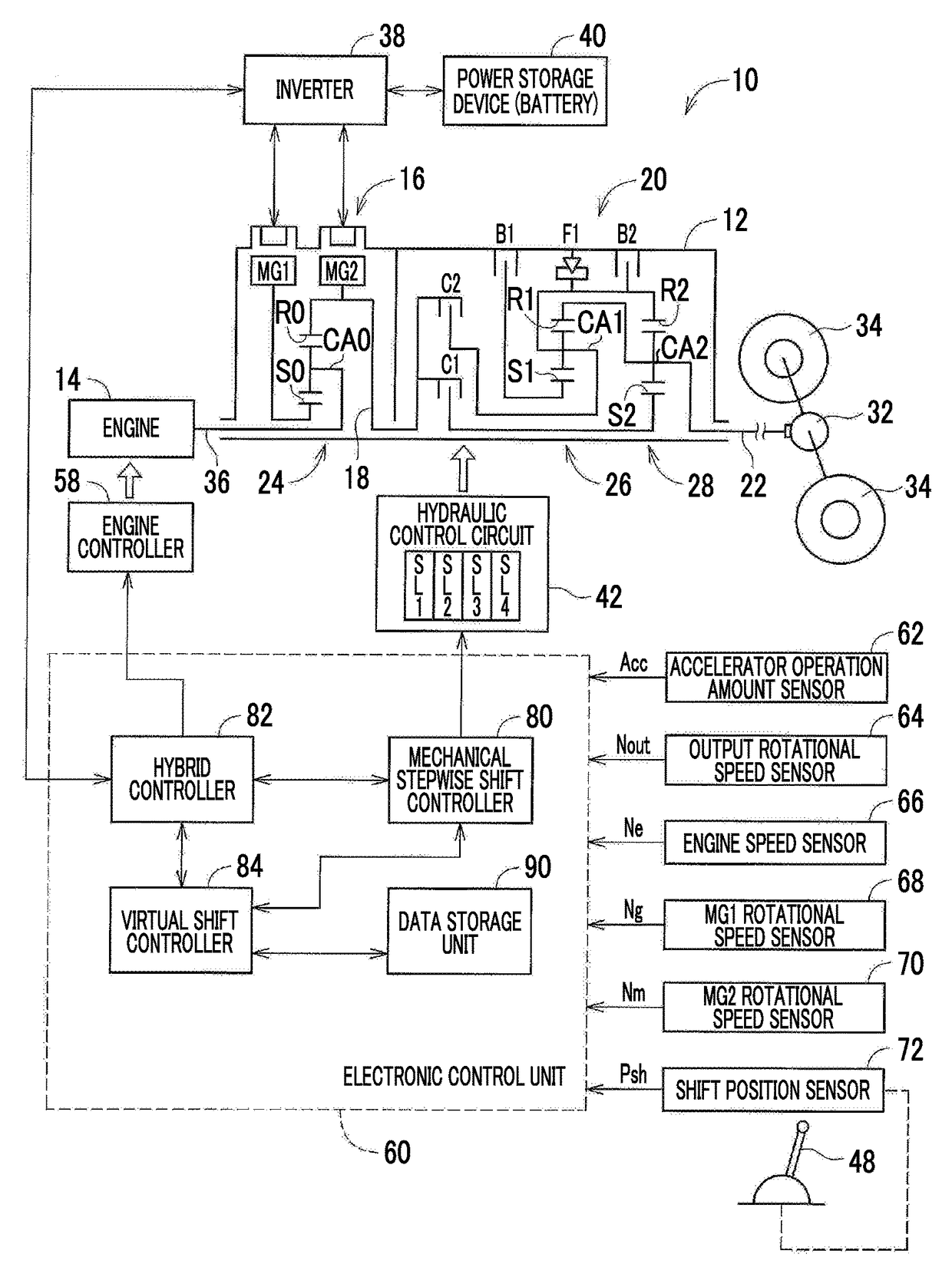
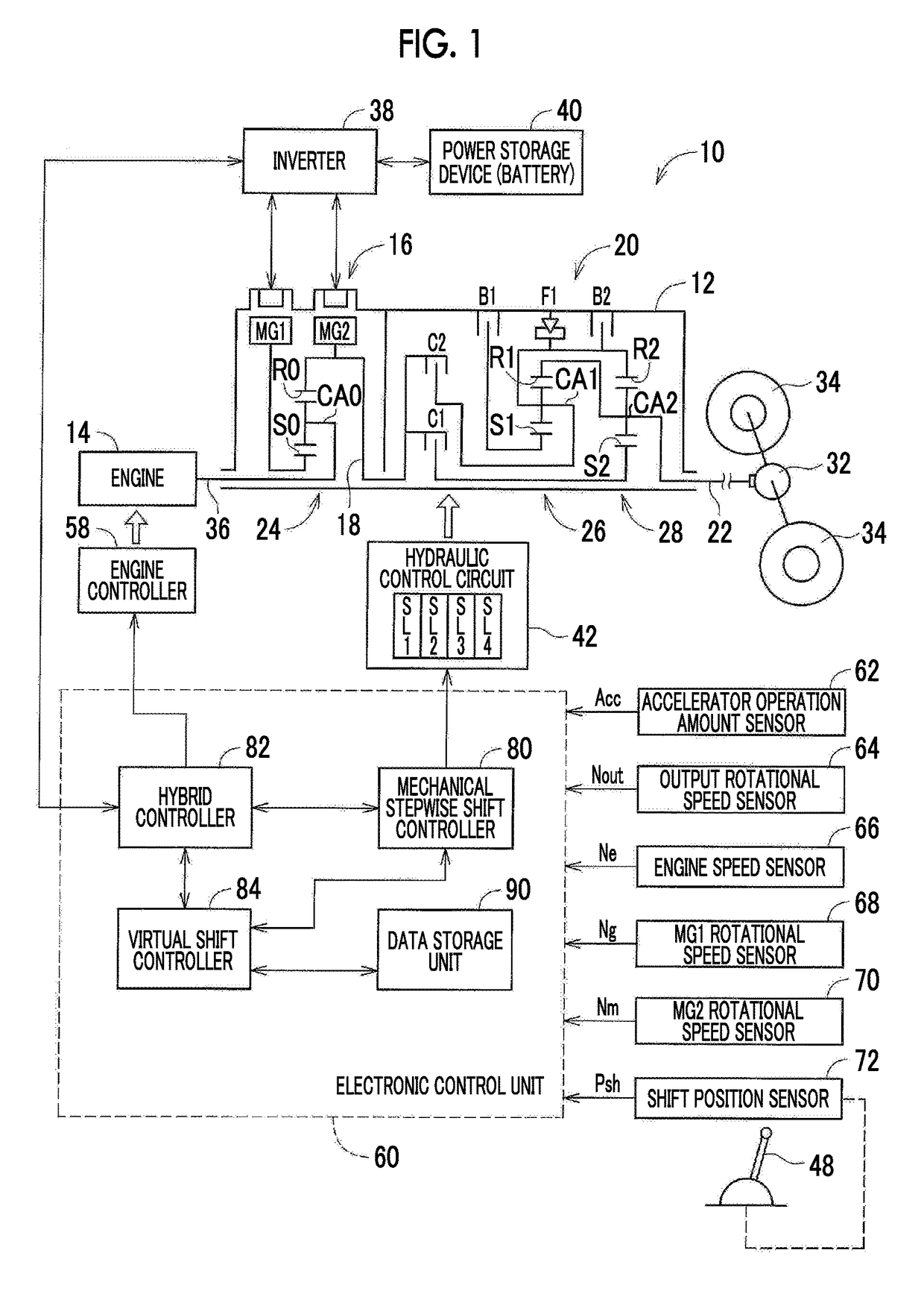
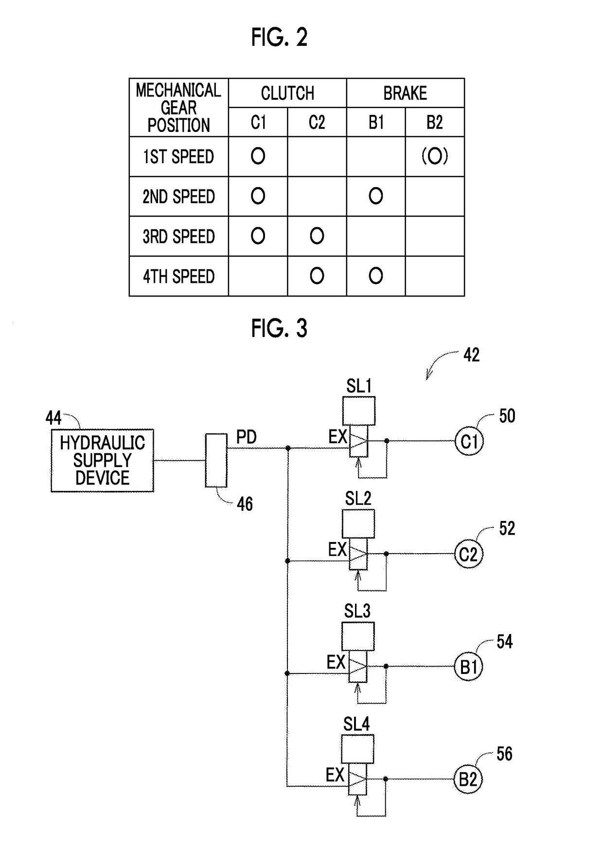
[0038]FIG. 1 is a skeleton diagram of a vehicular drive system (power transmission system) 10 according to a first embodiment, and also shows a principal part of a control system associated with shift control. As shown in FIG. 1, the vehicular drive system 10 includes an engine 14, an electric continuously variable transmission 16, a mechanical stepwise variable transmission 20, and an output shaft 22, which are connected in series and disposed on a common axis within a transmission case 12 (which will be called “case 12”) as a non-rotating member mounted on the vehicle body. The electric continuously variable transmission 16 is connected to the engine 14 directly or indirectly via a damper (not shown), or the like. The mechanical stepwise variable transmission 20 is connected to the outp...


PUM


Abstract

A plurality of virtual gear positions are established by an electric continuously variable transmission, and the number of speeds of the virtual gear positions is equal to or larger than the number of speeds of mechanical gear positions of a mechanical stepwise variable transmission. One virtual gear position or two or more virtual gear positions is / are assigned to each mechanical gear position, and the mechanical gear position is shifted in the same timing as shift timing of the virtual gear position. The virtual gear positions assigned to each mechanical gear position when the mechanical gear position is upshifted are different from the virtual gear positions assigned to each mechanical gear position when the mechanical gear position is downshifted. Thus, the amount of heat generated in frictional engagement elements of the mechanical stepwise variable transmission is prevented from being increased.

Description

INCORPORATION BY REFERENCE[0001]The disclosure of Japanese Patent Application No. 2016-089007 filed on Apr. 27, 2016 including the specification, drawings and abstract is incorporated herein by reference in its entirety.BACKGROUND[0002]1. Technical Field[0003]The disclosure relates to a hybrid vehicle. In particular, the disclosure is concerned with a hybrid vehicle including a power transmission system in which an electric continuously variable transmission and a mechanical stepwise variable transmission are connected in series.[0004]2. Description of Related Art[0005]A hybrid vehicle including a power transmission system in which an electric continuously variable transmission and a mechanical stepwise variable transmission are connected in series is known, as disclosed in Japanese Patent Application Publication No. 2006-321392 (JP 2006-321392 A). The electric continuously variable transmission can steplessly change the rotational speed of a drive source (an engine) through torque ...

Claims


Application Information

Patent Timeline
Patent Type & Authority Patents(United States)
IPC IPC(8): B60W10/105B60K6/547B60K6/365B60K6/387F16H3/72B60W20/30B60K6/543B60W10/115F16D67/04
CPCB60W20/30B60K6/387B60K6/543B60K6/547B60W10/105B60W10/115F16H3/728B60K6/365Y10S903/919B60W2550/00B60W2710/10B60Y2200/92B60Y2300/182B60Y2400/72B60Y2400/73F16D67/04Y10S903/911Y10S903/914Y10S903/918B60K6/445B60W10/06B60W10/08B60W2510/0638B60W2510/081B60W2540/10B60W2710/1005F16H3/727F16H37/042F16H61/04F16H61/702Y02T10/62B60W2555/00
Inventor BABA, MASAYUKIISOBE, ICHIRO
Owner TOYOTA JIDOSHA KK
Learn More