
Needle Cover for a Medical Injection Device

a technology for injection devices and needle covers, which is applied in the direction of infusion needles, intravenous devices, infusion syringes, etc., can solve the problems of physical inaccessibility of needles by users around the device, relatively difficult to remove needles from the tip, and user strength reduction, etc., and achieve the effect of reducing the pull out for

Pending Publication Date: 2021-12-09
BECTON DICKINSON FRANCE
View PDF3 Cites 3 Cited by
  • Summary
  • Abstract
  • Description
  • Claims
  • Application Information

AI Technical Summary

Benefits of technology

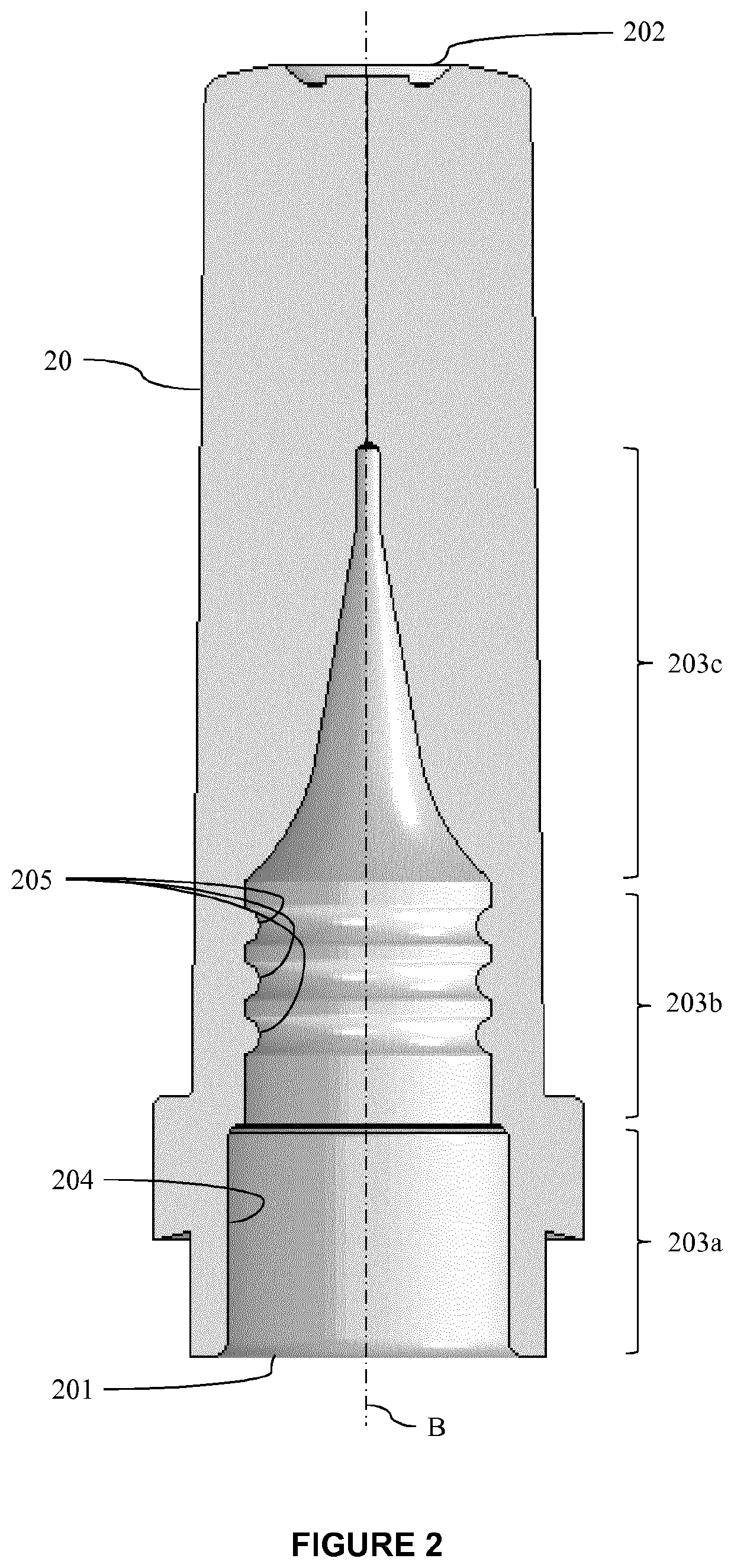
The patent is about a needle cover for a medical injection device that reduces the force needed to remove it while still making a tight seal with the tip of the device. The cover has ribs that are rounded and smoother on top, which helps to evenly distribute pressure over the surface of the injection device and further reduces the force required to remove the cover.

Problems solved by technology

This renders the needle physically inaccessible by the persons around the device.
A drawback of the known needle covers is that it may be relatively difficult to remove them from the tip.
As a consequence, a user having a reduced strength, for example weakened by a disease, may not be able to remove the needle shield and use the injection device for his treatment.

Method used


Image

  • Needle Cover for a Medical Injection Device
  • Needle Cover for a Medical Injection Device
  • Needle Cover for a Medical Injection Device

Examples


example 1

[0093]Three different designs of inner needle shields 20, noted M, are molded in thermoplastic elastomer. These inner needle shields are represented on FIG. 4. The features of these needle shields are described below and in Table 1.

TABLE 1molded needle shieldsRadiusHeightGapDDesign(mm)(mm)(mm)(mm)M1 (large0.40.251.073.8ribs)M2 (small0.20.10.713.8ribs)M3 (standardN / AN / AN / A3.8smooth)

[0094]“Radius” (R) refers to the radius (width) of each rib; “height” (H) refers to the height of each rib; “gap” (G) refers to the distance between two adjacent ribs; and “D” refers to the internal diameter of the inner needle shield, at the inner sealing portion. For ribbed designs, the diameter is measured at the top of a rib, as illustrated in FIG. 4, when the inner needle shield is not inserted on a syringe's tip. For all the designs M1, M2, M3, the needle shield is in TPE and the injection device is a glass syringe.

[0095]The designs M1, M2, M3 illustrated in FIG. 4 will be described also in reference...

example 2

nt of Different Designs for the Sealing Surface of the Needle Cover

[0115]In order to study the influence of the dimensions of the ribs, as well as their number, on the pull out force, a finite element analysis has been performed. Thermoplastic elastomer material properties (similar to material molded in example 1) are used for this finite element analysis. The removal of the needle cover is simulated and the pull out force is calculated.

[0116]Simulated designs for the sealing portion of the needle cover are described below in Table 3.

TABLE 3alternative designs for the sealing portion of the needle coverSchematicTrialDesignStructural featuresview1M1No change vs. M1FIG. 8AR = 0.4 mmdesignG = 1.07 mmH = 0.25 mm2M2No change vs. M2FIG. 8BR = 0.2 mmdesignG = 0.71H = 0.1 mm3M1, with R = 0.55 mmInfluence of the rib'sFIG. 8Cradius (+)4M1, with R = 0.2 mmInfluence of the rib'sFIG. 8Dradius (−)5M1, with G = 0.8 mm4 ribsFIG. 8E6M1, with only 2 ribs,2 ribsFIG. 8Fand G = 1.07 mm7M1, with only 1 r...


PUM


Abstract

The disclosure relates to a needle cover for protecting a needle mounted on a tip of a medical injection device. The tip comprises a distal bulge. The needle cover comprises an inner needle shield made of a material with elastomeric properties. The inner needle shield comprises an inner sealing portion configured to sealingly contact the outer surface of the bulge, wherein the inner sealing portion comprises one or more ribs extending inwardly along the circumference of the inner sealing portion. At least one rib is a continuous rib in the form of a ring configured to provide a continuous contact with the outer surface of the bulge.

Description

CROSS-REFERENCE TO RELATED APPLICATIONS[0001]This application is the United States national phase of International Application No. PCT / EP2019 / 078585 filed Oct. 21, 2019, and claims priority to European Patent Application No. 18306403.9 filed Oct. 26, 2018, the disclosures of which are hereby incorporated by reference in their entirety.BACKGROUND OF THE INVENTIONField of the Invention[0002]The disclosure relates to a needle cover adapted to be mounted on a tip of a medical injection device for covering a needle attached thereon. The disclosure also relates to a medical assembly for use in delivering a medical composition to a body of a patient, comprising a medical injection device and a needle cover for enclosing the needle of the medical injection device.Description of Related Art[0003]Medical injection devices such as syringes typically include a container for containing a medical composition having an end piece in a form of a longitudinal tip defining a fluid path through which t...

Claims


Application Information

Patent Timeline
Patent Type & Authority Applications(United States)
IPC IPC(8): A61M5/32
CPCA61M5/3202A61M2005/3109
Inventor POUGET, GAËLLEOZTURK, SENTURK
Owner BECTON DICKINSON FRANCE
Learn More