
Time domain calculation method of voltage traveling-wave differential protection for vsc-hvdc transmission lines

a technology of vsc-hvdc transmission lines and time domain calculations, which is applied in the direction of impedence measurement, fault location by conductor types, instruments, etc., can solve the problems of long time delay, inability to meet the speed requirement of vsc-hvdc systems, and extreme threats to system and device security, etc., to achieve accurate and rapid detection of internal faults

Active Publication Date: 2021-12-02
TIANJIN UNIV
View PDF0 Cites 3 Cited by
  • Summary
  • Abstract
  • Description
  • Claims
  • Application Information

AI Technical Summary

Benefits of technology

The present invention provides a new method for protecting VSC-HVDC transmission lines that takes into account the frequency-dependent characteristics of line parameters. This method allows for more accurate and rapid detection of internal faults, and can be used as the main protection when the length of the transmission line is not too long. The method is easy to implement and shortens the delay while ensuring calculation accuracy. The technical effects of this invention include improved fault identification and protection, ensuring the safe operation of VSC-HVDC transmission lines.

Problems solved by technology

Due to the small damping at DC side, the current suddenly rises and voltage drops rapidly when a short circuit occurs on the VSC-HVDC transmission line, which will extremely threaten the security of system and device.
The conventional longitudinal differential protection has the advantages such as good selectivity and high sensitivity, but also has long time delay and cannot meet the speed requirement of the VSC-HVDC system.

Method used


Image

  • Time domain calculation method of voltage traveling-wave differential protection for vsc-hvdc transmission lines
  • Time domain calculation method of voltage traveling-wave differential protection for vsc-hvdc transmission lines
  • Time domain calculation method of voltage traveling-wave differential protection for vsc-hvdc transmission lines

Examples


Embodiment Construction

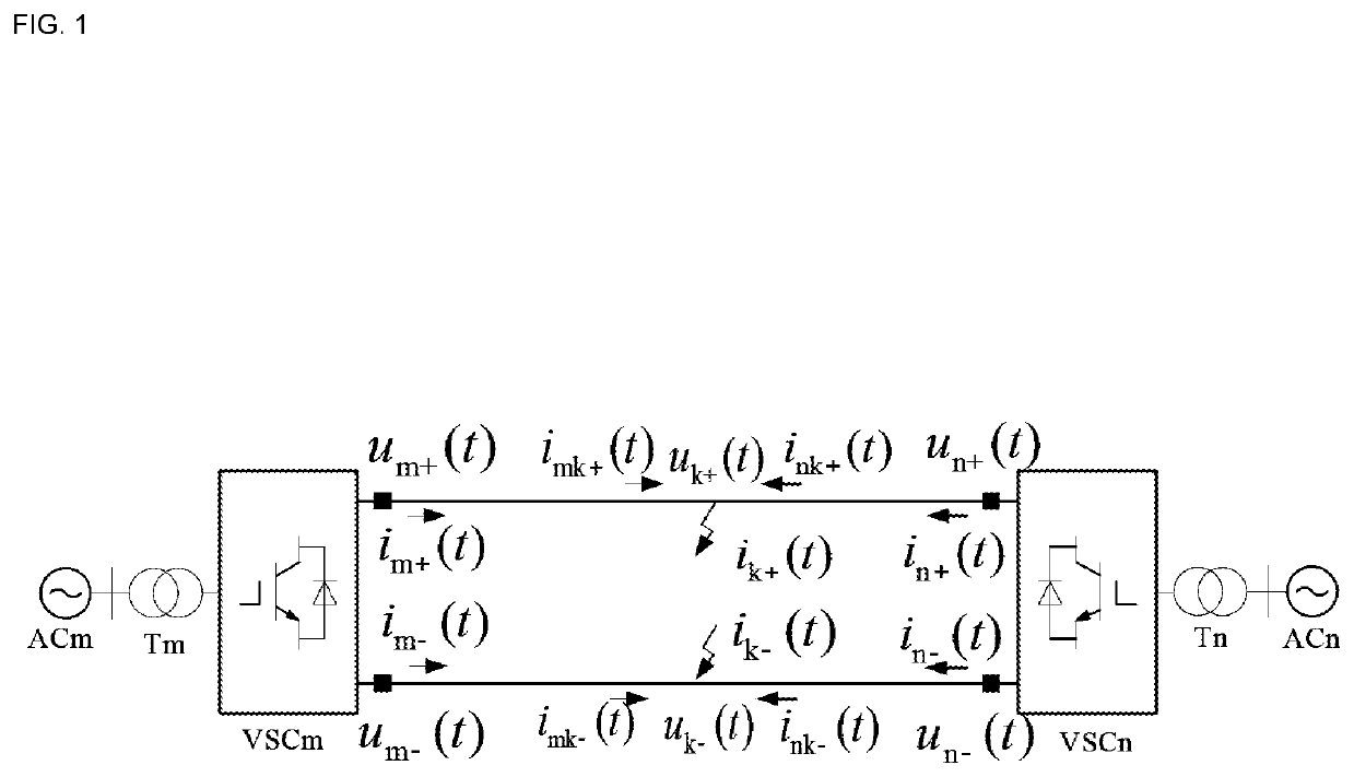
b class="d_n">[0070]In order to overcome the defects of the prior art, the present invention provides a calculation method of voltage travelling-wave differential protection for VSC-HVDC transmission lines. The method of the present invention collects the electrical quantity in time domain at the both ends of the transmission line, establishes the frequency-dependent modeling functions of the VSC-HVDC transmission line for calculating the voltage traveling-wave values at both ends, and finally calculates differential value so as to identify whether internal fault occurs. The method can on-line calculate voltage traveling-wave values of the line according to the real-time collected electrical quantity, and can shorten the delay during calculation so as to satisfy the requirements of speed and selectivity of VSC-HVDC system.

[0071]The technical scheme of the present invention is as follows: a calculation method of voltage travelling-wave differential protection for VSC-HVDC transmissio...


PUM


Abstract

The present invention related to the field of power system protection and control, presents a voltage travelling wave differential protection method considering the influence of frequency-dependent parameters, which provides more accurate and rapid fault identification. The technical scheme of the present invention is as follows: a calculation method of voltage travelling-wave differential protection for VSC-HVDC transmission lines, taking the influence of the frequency-dependent parameters into consideration, the steps are as follows: calculating a characteristic impedance and propagation coefficient of the frequency-dependent transmission line in time domain, collecting voltage and current signals at the both ends of the transmission line and then calculating the forward and backward voltage travelling wave, respectively, comparing a differential value of voltage travelling wave with a preset threshold value to determine whether the internal fault occurs.The present invention is mainly applied in the field of power system protection and control.

Description

TECHNICAL FIELD[0001]The invention relates to the field of power system protection and control, especially to the travelling-wave differential protection of VSC-HVDC transmission lines, and proposes a calculation method of voltage travelling-wave differential protection for VSC-HVDC transmission lines considering the frequency-dependent line parameters.BACKGROUND OF THE PRESENT INVENTION[0002]Voltage Source Converter Based High Voltage Direct Current (VSC-HVDC) is a novel High Voltage Direct Current (HVDC) based on Voltage Source Converter (VSC) and full-controlled turn-off electronic device. The VSC-HVDC has the advantages such as high economic efficiency, flexibility and environmental friendly protection, and is one of the key techniques in the research and application of smart grid. At present, the VSC-HVDC adopts Modular Multilevel converters (MMC) to convert AC to DC. Due to the small damping at DC side, the current suddenly rises and voltage drops rapidly when a short circuit ...

Claims


Application Information

Patent Timeline
Patent Type & Authority Applications(United States)
IPC IPC(8): G01R31/08
CPCG01R31/088G01R31/085G01R19/2513H02H7/265G01R27/16
Inventor LI, BOTONGLV, MINGRUILI, BIN
Owner TIANJIN UNIV
Learn More