Venous valve with enhanced flow properties

a technology of venous valves and flow properties, applied in the field of medical devices, can solve the problems of limiting the diameter becomes the limiting factor in the ability of the valve assembly to compress into a decreased delivery profile, and the balloon with a large outer profile is difficult to insert into the patient's vein position, etc., to avoid high fluid resistance to forward venous blood flow, reduce the delivery profile, and minimize the potential for thrombo

Pending Publication Date: 2021-12-02
INNOVEIN INC
View PDF2 Cites 1 Cited by
  • Summary
  • Abstract
  • Description
  • Claims
  • Application Information

AI Technical Summary

Benefits of technology

[0010]The mechanical nature of the prosthetic ball valve confers durability to the implant, thereby removing the modes of valve failure observed in prosthetic leaflet valves. With a ball valve, no leaflets are present that may thicken, tear or prolapse. In the prosthetic venous ball valve, the failure mode is limited to clot formation (or “thrombosis”). Therefore, it is desirable to incorporate a ball design and retention system that minimize the potential for thrombus formation within the structure of the valve assembly. Thrombus formation is dependent on the characteristics of blood flow (hemodynamics) through the valve, where flow is maintained inside the lumen formed by the implant's anchoring portion and over the mobile ball component. The orifice size of the valve seat should be maximized to avoid high fluid resistance to forward venous blood flow. Maximizing the valve seat orifice size and the ball size (which is oversized relative to the orifice to contact the valve seat), however, creates a ball with a large outer profile that is difficult to insert into position in a patient's vein. If a venous valve implant contains a self-expanding frame (or even a balloon expandable frame), the frame may reside in a compressed configuration for delivery into the vein. If a rigid ball is used in the valve assembly, its diameter becomes the limiting factor in the ability for the valve assembly to compress into a decreased delivery profile. Thus, a compressible ball is included in many embodiments described herein, to minimize the delivery system profile of the prosthetic venous valve implant. In an alternative embodiment, the ball and the orifice have similar diameters, and the ball resides fully within the orifice (thereby acting like a “plug”) when the ball is in the closed position. This configuration may allow for a smaller ball and / or a larger valve seat orifice, either or both of which may help reduce forward blood flow resistance.
[0011]Implants constructed with foreign materials can lead to clot formation in the bloodstream. The characteristics of blood flowing through the valve may also contribute to thrombus formation. When the valve opens due to forward blood flow, the ball moves out of contact with the valve seat due to forward pressure to its “open” position, as allowed by the retention constraints. The valve closes due to retrograde flow and elastic spring force (in some embodiments), creating a pressure reversal on the ball and the ball moves back into contact with the valve seat. During the excursions of the ball in and out of contact with the valve seat, the flow conditions are in a transitory state for a short duration of time. When the ball is in the open position, however, the path of blood between the ball and the inner surface of the frame should ideally be uniform (i.e., laminar flow, no stagnant areas, etc.). Maintaining a uniform flow path area between the ball and the inner surface of the frame avoids changes in blood flow velocity that lead to eddy currents and areas of static blood flow at different locations within the valve assembly. Areas of stasis in the valve contribute to clot formation or thrombosis. Additionally, venous blood flow is susceptible to thrombogenesis when wall shear rates are too low or too high. Optimally, wall shear rates of venous implants may be designed to be within a desired range, to mitigate thrombus formation. Further, if implanted devices are too restrictive with respect to forward flow back to the heart, alternative flow paths around the device in the target vessel or in nearby vessels may develop, which may lead to thrombogenesis due to reduced flow and stagnation in the implant. It is therefore believed that a prosthetic venous valve assembly should have low resistance to forward flow. This is achieved by designing the prosthetic venous valve assembly to have a low pressure drop for a given flow rate and low stiffness for embodiments with an elastic retention system. The venous valve prosthetic devices described herein include features and design characteristics that advantageously address many if not all of these issues of flows, shear, thromobogenesis and the like.
[0012]Embodiments of a venous valve implant are described in this application for improving the fluid flow within the vascular valve assembly. In most if not all embodiments, the ball of the implant (or “the valve component”) is collapsible / expandable (or “non-rigid”). It is desirable to modulate the axial position of the ball as a function of flow rate, and the embodiments herein include features to address this goal. For low flow rates, the ball may be elastically pulled to the closed position (or nearly closed) at the waist with low force, to enable valve motion (i.e., flutter). This position at low flow rates prevents the ball from resting on the frame (valve stasis) further downstream, which may cause occlusion of the implantable valve. Conversely, in order to accommodate relatively large flow rates (e.g., during exercising), the ball moves to a more open, less restrictive position to mitigate high wall shear rates that may lead to thrombus (clot) formation. Thus, embodiments described herein provided a variable position valve according to variable input flow rates, thereby helping reduce thrombus formation at both low and high flow rates.
[0027]In some embodiments, the elastic component is a spring disposed over a main tether member and attached to the anchoring frame. In some embodiments, the ball and the ball retention tether are configured so that the ball moves between an open position, in which the ball is located downstream of the valve seat, and a closed position, in which the ball is located closer to the valve seat or contacts the valve seat, to reduce or prevent backflow of blood. In some embodiments, the ball is expandable from a compressed configuration for delivery into the vein through a catheter to an expanded configuration outside the catheter.

Problems solved by technology

Maximizing the valve seat orifice size and the ball size (which is oversized relative to the orifice to contact the valve seat), however, creates a ball with a large outer profile that is difficult to insert into position in a patient's vein.
If a rigid ball is used in the valve assembly, its diameter becomes the limiting factor in the ability for the valve assembly to compress into a decreased delivery profile.

Method used


Image

  • Venous valve with enhanced flow properties
  • Venous valve with enhanced flow properties
  • Venous valve with enhanced flow properties

Examples


Embodiment Construction

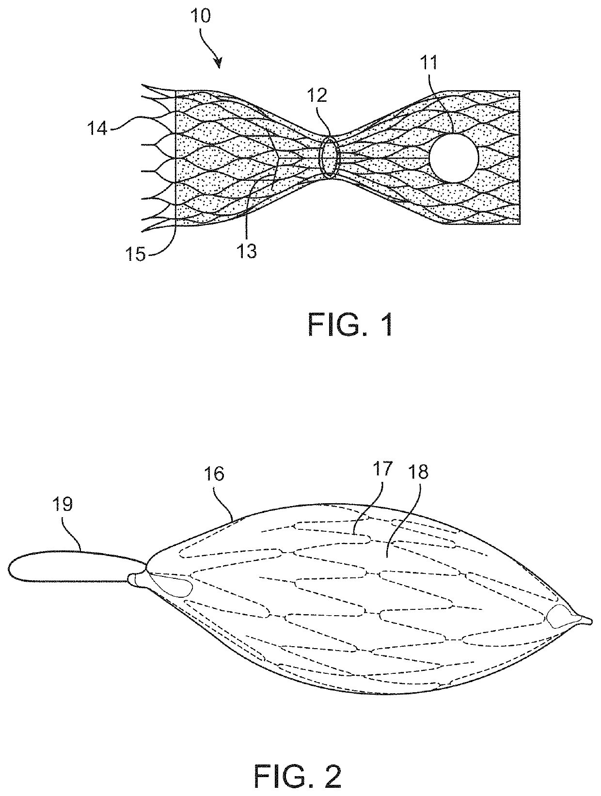
[0073]In this disclosure, the term “proximal” will be used synonymously with “upstream,” and the term “distal will be used synonymously with “downstream.”“Upstream,” in this disclosure, means farther away from the heart, in other words upstream when blood is flowing toward the heart. “Downstream,” in this disclosure, means closer to the heart, in other words downstream when blood is flowing toward the heart. Although in a vein blood sometimes flows in a retrograde direction (i.e., away from the heart, for example between heartbeats), the terms upstream and downstream in this disclosure refer to blood flow in the direction toward the heart. Similarly, “forward flow” means blood flow in a direction toward the heart, and “retrograde flow” or “backward flow” means blood flow in a direction away from the heart. “Horizontal flow” or “in a horizontal direction,” refers to blood flow in a direction straight through the blood vessel and / or the valve implant device. This definition is used re...


PUM


Abstract

A prosthetic venous valve includes an expanding anchoring frame, a valve seat at the middle portion of the anchoring frame, a ball disposed within the lumen of the anchoring frame and having an outer diameter, and least one ball retention tether coupled with the ball and the anchoring frame. The ball retention tether includes at least one elastic component or material. The anchoring frame has an upstream end, a downstream end, a middle portion and a lumen extending through the anchoring frame from the upstream end to the downstream end. The ball moves between an open position, in which the ball is located apart from the valve seat, and a closed position, in which the ball is located in contact with or near the valve seat to reduce or prevent backflow of blood through the prosthetic venous valve.

Description

CROSS-REFERENCE TO RELATED APPLICATIONS[0001]This application claims the benefit of U.S. Provisional Patent Application No. 63 / 033,312, filed Jun. 2, 2020, entitled, “VENOUS VALVE WITH ENHANCED FLOW PROPERTIES.” The disclosure of this priority application is hereby incorporated by reference in its entirety into the present application.TECHNICAL FIELD[0002]This application relates generally to the field of medical devices. More specifically, the application relates to prosthetic valve implant devices, systems and methods for implantation within the vasculature.BACKGROUND[0003]Veins in the human body are weak-walled blood vessels that carry blood under low pressures back to the heart from the extremities. To help move the blood toward the heart, most frequently against the force of gravity, veins have one-way valves, which open in the direction of forward-moving blood flow and close to prevent backflow of blood. When these valves become compromised, the veins cannot function properly....

Claims


Application Information

Patent Timeline
Patent Type & Authority Applications(United States)
IPC IPC(8): A61F2/24
CPCA61F2/2475A61F2230/0076A61F2230/0071A61F2/2424A61F2250/0039A61F2/91
Inventor EHNES, DALE L.WOODSON, TERESASTAUDENMAYER, CHRISTOPHERWALKER, AUSTINKRAMER, THOMASCHIN, ALBERT K.GEUSEN, MARK
Owner INNOVEIN INC
Why Eureka
Try Eureka