Chain guide and chain transmission device using same

Pending Publication Date: 2021-11-04
DAIDO KOGYO CO LTD
View PDF0 Cites 0 Cited by
  • Summary
  • Abstract
  • Description
  • Claims
  • Application Information

AI Technical Summary

Benefits of technology

The patent is about improving the chain guide of a device by adding oil to the guide groove to increase its holding force and reduce friction. However, this can cause problematic noise and wear on the chain guide due to the intermittent contact with the chain. The technical effect is to solve this problem by reducing the contact pressure and noise while also increasing the chain guide's wear-resistance.

Problems solved by technology

As a result, frictional resistance is generated in a travel of the chain 104, and an energy loss is generated in the transmission of the timing chain transmission device 101.

Method used


Image

  • Chain guide and chain transmission device using same
  • Chain guide and chain transmission device using same
  • Chain guide and chain transmission device using same

Examples


Embodiment Construction

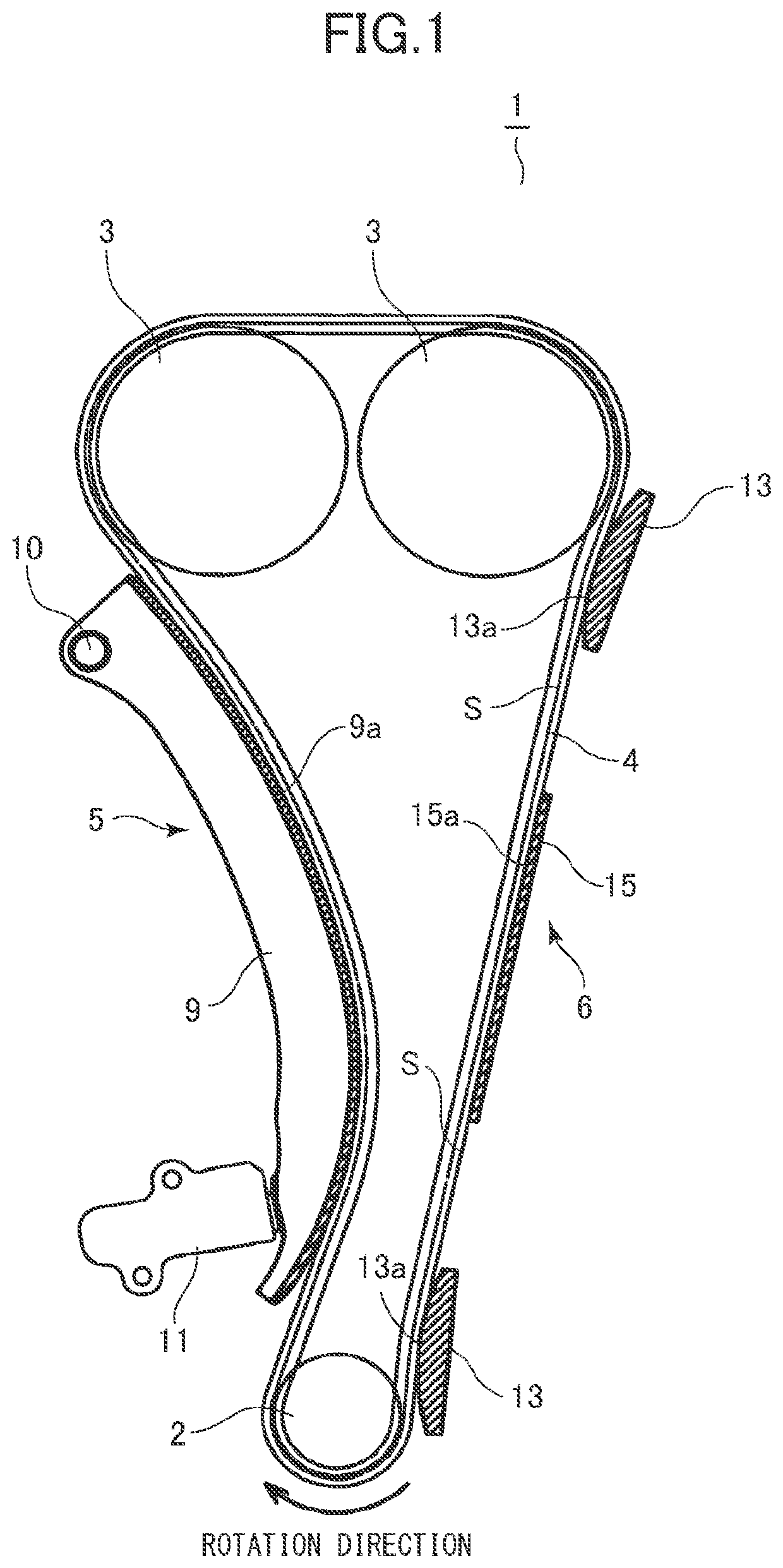
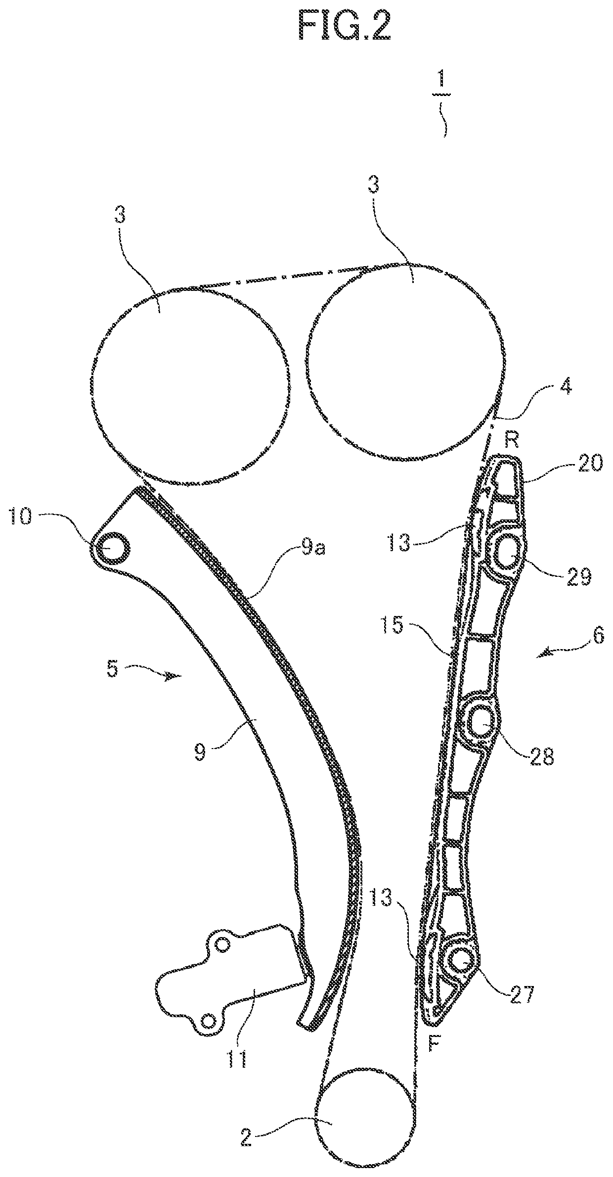
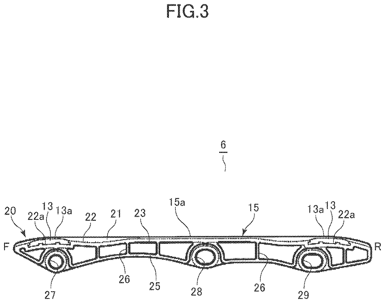
[0029]Hereinafter, embodiments of the invention will be described with reference to the drawings. The present embodiment is applied to a timing chain transmission device that transmits rotation of an engine crankshaft to a camshaft. As shown in FIGS. 1 and 2, in the chain transmission device 1, a chain 4 is wound between an engine crank sprocket 2 on a drive side and two cam sprockets 3, 3 on a driven side. The chain 4 is preferably a silent chain, but is not limited thereto, and may be another transmission chain such as a roller chain or a bushing chain.

[0030]In the chain transmission device 1, a chain tensioner 5 is disposed to be in sliding contact with a slack side outer surface of the chain 4, and a chain guide 6 is disposed to be in sliding contact with a tension side outer surface of the chain 4. The chain tensioner 5 includes an arcuate member 9 made of a synthetic resin, a steel plate, or the like having wear resistance. An arcuate sliding contact surface 9a of the arcuate ...


PUM


Abstract

A chain guide includes a contact guide portion that comes into contact with a chain and guides the chain, and a vibration control portion having a zero-touch surface extending along a travel line of the chain.

Description

CROSS-REFERENCE TO RELATED APPLICATIONS[0001]This application is a Continuation of International Patent Application No. PCT / JP2020 / 1994, filed Jan. 21, 2020, which claims the benefit of Japanese Patent Application No. 2019-008802, filed Jan. 22, 2019, both of which are hereby incorporated by reference herein in their entirety.BACKGROUND OF THE INVENTIONField of the Invention[0002]The present invention relates to a chain guide that comes into contact with a chain to guide the chain, and a chain transmission device using the same.Description of the Related Art[0003]In general, as shown in FIGS. 9A and 9B, a chain transmission device, for example, a timing chain transmission device 101 disposed in an engine, includes a crank sprocket 102, a cam sprocket 103, and a chain 104 wound between the crank sprocket 102 and the cam sprocket 103. A chain tensioner 105 is disposed on a slack side of the chain 104, and a chain guide 106 is disposed on a tension side of the chain 104. The chain guid...

Claims


Application Information

Patent Timeline
IPC IPC(8): F16H7/18F16H7/08F16H7/06
CPCF16H7/18F16H7/08F16H2007/0893F16H2007/185F16H2007/0872F16H7/06
Inventor NAOE, TOSHIYASEKI, HIDEAKI
Owner DAIDO KOGYO CO LTD
Why Eureka
Try Eureka