
Rotation angle detection method and device thereof

Active Publication Date: 2021-10-28
UBTECH ROBOTICS CORP LTD
View PDF0 Cites 1 Cited by
  • Summary
  • Abstract
  • Description
  • Claims
  • Application Information

AI Technical Summary

Benefits of technology

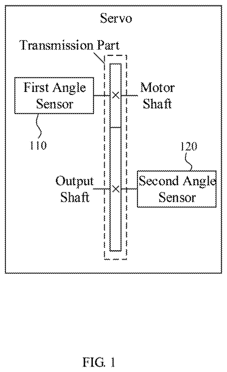
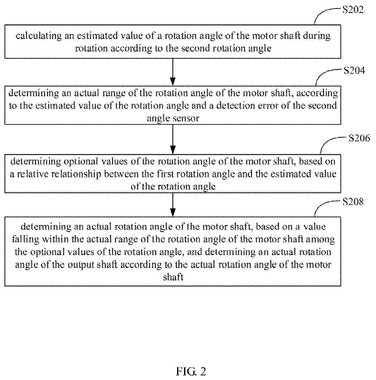
The present invention provides a method and device for detecting the rotation angle of an output shaft of a rotating mechanism with improved accuracy. This is achieved by using two angle sensors, one on the motor shaft and one on the output shaft, to detect the rotation angles. The method calculates the estimated value of the rotation angle of the motor shaft based on the second rotation angle and the detection error of the second angle sensor. The actual range of the rotation angle of the motor shaft is determined based on the estimated value and the detection error of the second angle sensor. The optional values of the rotation angle of the motor shaft are determined based on the relative relationship between the first rotation angle and the estimated value. The actual rotation angle of the motor shaft is determined based on the value falling within the actual range of the rotation angle of the motor shaft among the optional values. This method improves the measurement accuracy of the rotation angles of the output shaft and reduces the influence of the accuracy error of the angle sensor on the overall error of the system, resulting in more accurate output control of the rotating mechanism.

Problems solved by technology

In this solution, the error of the angle sensor itself is directly introduced to the control of the rotation angle of the output shaft, and so it is difficult to bring accurate control effect.

Method used


Image

  • Rotation angle detection method and device thereof
  • Rotation angle detection method and device thereof
  • Rotation angle detection method and device thereof

Examples


Embodiment Construction

[0045]In order to make the purpose, technical solutions and advantages of the present application clearer, the present application is further described in detail below in combination with the drawings and embodiments. It should be understood that the specific embodiments described herein are used only to explain the present application, and are not used to limit the present application.

[0046]Unless otherwise defined, all technical and scientific terms used herein have the same meanings as generally understood by one of ordinary skill in the art of the present application. The terms used herein in the specification of the present application are only for the purpose of describing specific embodiments, and are not intended to limit the present application. It will be understood that, although the terms “first”, “second”, etc. may be used herein to describe various elements, these elements should not be limited by these terms. These terms are only used to distinguish one element from a...


PUM


Abstract

The present invention provides a rotation angle detection method and device thereof. The method includes calculating an estimated value of a rotation angle of a motor shaft during rotation according to a second rotation angle; determining an actual range of the rotation angle according to the estimated value of the rotation angle and a detection error of the second angle sensor; determining optional values of the rotation angle based on a relative relationship between a first rotation angle and the estimated value; determining an actual rotation angle of the motor shaft, based on a value falling within the actual range of the rotation angle among the optional values, and determining an actual rotation angle of the output shaft according to the actual rotation angle of the motor shaft. The present invention can improve the measurement accuracy of the rotation angles of the output shaft of the rotating mechanism.

Description

BACKGROUND1. Technical Field[0001]The present disclosure generally relates to measurement and control technology, and particularly to a rotation angle detection method and device thereof.2. Description of Related Art[0002]A servo is a position (angle) servo drive applied to a control system that needs to constantly change angles and can maintain the angles. One of the main tasks for the servo is to be able to accurately control rotation angles of the output shaft. The accuracy of the rotation angle control of the output shaft of the servo depends on the detection accuracy of the real-time rotation angle of the output shaft. That is to say, only on the premise of the real-time rotation angle of the output shaft being accurately calculated, the accurate control of the output shaft angle can be achieved by the control system.[0003]A traditional method for detecting the angle of the output shaft of the servo is usually to directly detect the rotation angle of the output shaft by an angl...

Claims


Application Information

Patent Timeline
IPC IPC(8): G01B5/24H02P21/18G05B19/416
CPCG01B5/24G05B2219/41036G05B19/416H02P21/18G01D3/036G01D5/24485
Inventor BAI, XIFAN, WENHUAWANG, MALINXIONG, YOUJUN
Owner UBTECH ROBOTICS CORP LTD
Learn More