
Method for controlling emissions of nitrogen oxides in exhaust of internal combustion engine

a technology of internal combustion engine and nitrogen oxide, which is applied in the direction of electric control, machines/engines, mechanical equipment, etc., can solve the problems of increasing stringent legal constraints, pollution of emissions, and the inability to guarantee that such a threshold will never be exceeded

Active Publication Date: 2021-10-28
NISSAN MOTOR CO LTD
View PDF0 Cites 0 Cited by
  • Summary
  • Abstract
  • Description
  • Claims
  • Application Information

AI Technical Summary

Benefits of technology

The invention proposes a method to control the amount of nitrogen oxides emitted from a vehicle over a set distance travelled. The method involves calculating the average amount of nitrogen oxides emitted per distance travelled and comparing it to a threshold. Depending on the outcome, the method determines parameters to optimize engine performance and reduce nitrogen oxide emissions. The technical effect is to provide a means to control and minimize emissions of nitrogen oxides from vehicles fitted with internal combustion engines.

Problems solved by technology

Reducing polluting emissions in exhaust of internal-combustion engines, and more specifically the internal-combustion engines in motor vehicles, which are subject to increasingly stringent legal constraints, is a strategic challenge.
Nonetheless, since this is a statistical approach, it is not possible to guarantee that such a threshold will never be exceeded for a specific real cycle, in particular in extreme usage conditions (for example a particularly severe cycle in terms of engine load or transients).

Method used


Image

  • Method for controlling emissions of nitrogen oxides in exhaust of internal combustion engine
  • Method for controlling emissions of nitrogen oxides in exhaust of internal combustion engine
  • Method for controlling emissions of nitrogen oxides in exhaust of internal combustion engine

Examples


Embodiment Construction

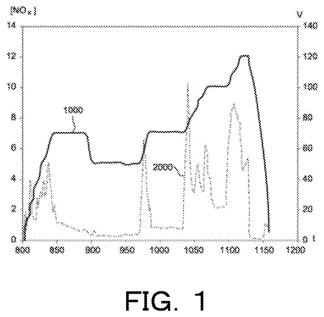
[0033]FIG. 1 has already been described above and requires no additional comment.

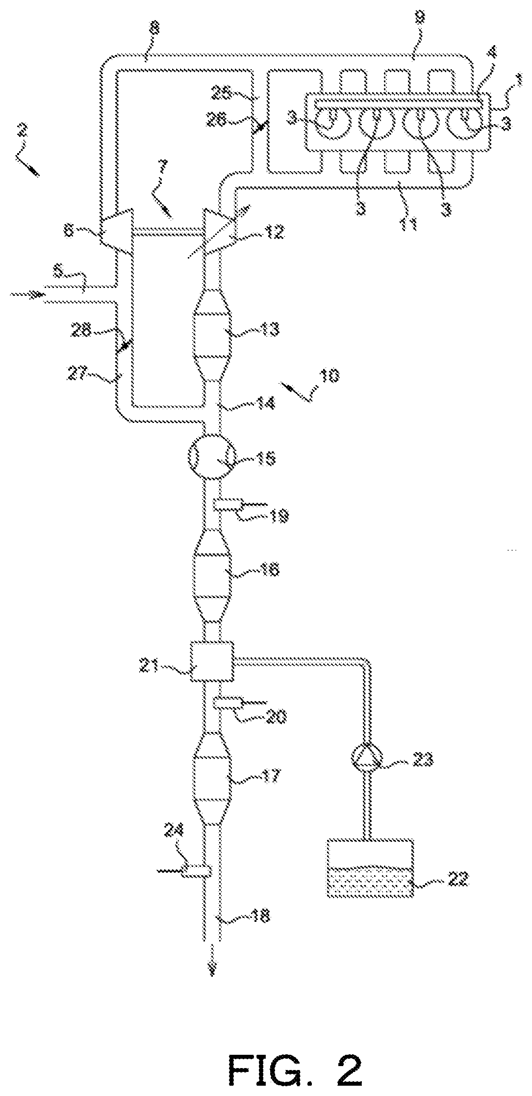
[0034]FIG. 2 shows a motorization device designed to implement the method according to the invention. This device is an internal combustion engine 1, for example a diesel engine of a motor vehicle, in this case a four-cylinder inline supercharged engine. The engine 1 is supplied with air by an air intake circuit 2 and with fuel, for example diesel, by a plurality of injectors 3 mounted on a fuel-injection common rail 4.

[0035]The air intake circuit 2 comprises, in an upstream to downstream direction, i.e. in the direction of air flow, an air intake line 5, a compressor 6 of a turbocharger 7 of the engine 1, a compressor-intake manifold connecting line 8, and a distributor or intake manifold 9. Naturally, the intake circuit 2 can include other components that are not shown here, for example an air filter, supercharged air cooler, etc.

[0036]The engine 1 is also equipped with an exhaust circuit 10 for exhau...


PUM


Abstract

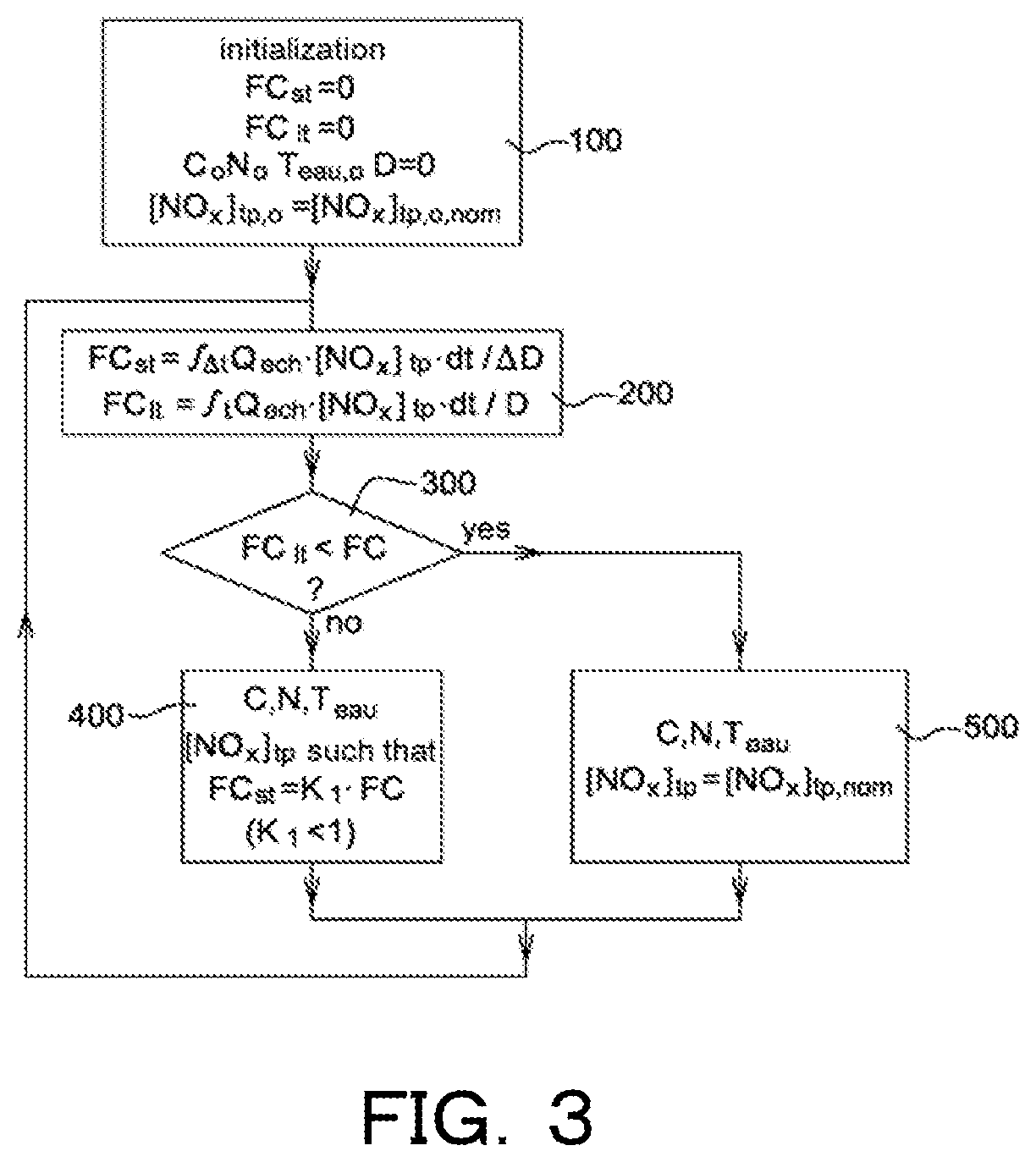
The invention relates to a control method that allows the mean quantity of nitrogen oxides per kilometer covered emitted by a vehicle fitted with an internal combustion engine associated with a post-treatment system to be kept below a predefined fixed threshold, for any journey made by the vehicle. The mean quantity emitted over a fixed elementary distance that has just been covered by the vehicle is calculated iteratively, together with a long-term conformity factor which is equal to the mean quantity emitted over the entire distance covered since the start of the journey. When it is found that the long-term conformity factor is above the threshold, the engine and / or the post-treatment system is regulated in such a way as to obtain, over the next fixed elementary distance, a mean quantity of nitrogen oxides per kilometer that is lower than the threshold value FC, for example equal to 90% of the threshold, whatever the engine operating point. Thus, the long-term conformity factor converges towards the threshold.

Description

TECHNICAL FIELD[0001]The invention relates to a method for controlling nitrogen oxide emissions from combustion gases of an internal-combustion engine, notably a diesel engine.BACKGROUND ART[0002]Reducing polluting emissions in exhaust of internal-combustion engines, and more specifically the internal-combustion engines in motor vehicles, which are subject to increasingly stringent legal constraints, is a strategic challenge.[0003]To do so, post-treatment systems for combustion gases from an internal-combustion engine are usually used to treat different types of pollutants (for example: carbon monoxide CO, unburnt hydrocarbons HC, nitrogen oxides NOx, soot, etc.) emitted in these gases.[0004]To limit more specifically discharge into the atmosphere of nitrogen oxide molecules (essentially nitrogen monoxide NO and nitrogen dioxide NO2), which are harmful to health and to the environment, many engines are fitted with an NOx trap and / or a selective reduction catalyst for nitrogen oxides...

Claims


Application Information

Patent Timeline
IPC IPC(8): F02D41/14F02D41/00F02D41/02F01N3/20
CPCF02D41/1463F02D41/0055F02D41/0275F02D41/0245F01N3/208F02D2200/023F01N2900/1402F02D2200/1002F02D2200/701F01N2900/102F01N2900/1812F01N2900/08F02D2200/101F01N3/2066F01N11/00F01N2560/026F01N2570/14F01N2610/02F02D2250/36F02D41/0235F02D29/02F02M26/05F02M26/06F02M26/15F02D41/0052Y02A50/20Y02T10/12Y02T10/40
Inventor VON WISSEL, DIRKABIDA, JAMIL
Owner NISSAN MOTOR CO LTD
Learn More