
Matching for GNSS signals

a technology of gnss signals and matching signals, applied in the field of navigation systems, can solve the problems of inaccurate position location of gnss receivers and urban canyons, and achieve the effects of less attenuation, improved pattern matching operations, and reduced polarization based distortion

Pending Publication Date: 2021-10-21
ONENAV INC
View PDF0 Cites 4 Cited by
  • Summary
  • Abstract
  • Description
  • Claims
  • Application Information

AI Technical Summary

Benefits of technology

The patent describes a method for improving GNSS signal reception in devices such as smartphones and vehicles. The method involves using a linear polarized antenna to receive the GNSS signals, which reduces polarization based distortions on the measured channel responses. This allows for more accurate pattern matching and location tracking. Additionally, the method includes determining the expected signal reception data for the GNSS satellites based on the device's location and the surrounding structures, and comparing it to the received GNSS signals for accurate location tracking.

Problems solved by technology

Urban canyons present problems for GNSS receivers because the tall buildings which line the streets of cities often block direct, line of sight signals from reaching the GNSS receiver.
As a result, position location in urban canyons can be inaccurate.
This inaccuracy can result in situations in which a driver of a taxi service (e.g., Uber) is directed to the wrong side of the street by the GNSS receiver of the potential passenger.

Method used


Image

  • Matching for GNSS signals
  • Matching for GNSS signals
  • Matching for GNSS signals

Examples


embodiment 1

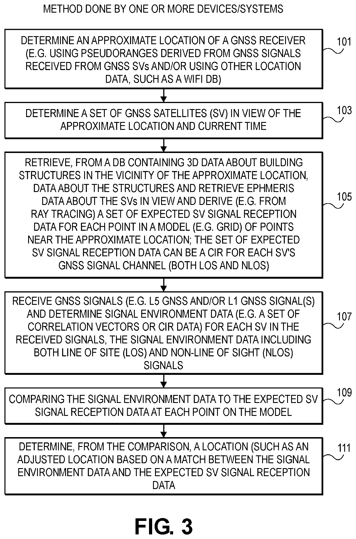
[0069] A method for processing GNSS signals, the method comprising:

[0070]determining an approximate location of a GNSS receiver;

[0071]determining a set of GNSS satellites (SV) in view of the approximate location;

[0072]receiving or generating, based on three dimensional (3D) data about structures in the vicinity of the approximate location, a set of data describing expected SV signal reception data for the SVs in view, the set of data including, for each point in a model of points near the approximate location, the expected SV signal reception data for each SV in view at each point in the model, the expected SV signals including both line of sight and non-line of sight signals from each SV in the set of SVs in view;

[0073]receiving, at the GNSS receiver, GNSS signals in at least one of the L5 band (“GNSS L5 signals”) and the L1 band and determining signal environment data for the received GNSS L5 signals or GNSS signals in the L1 band, the signal environment data including data for bo...

embodiment 2

[0076] The method as in claim 1 wherein the comparing comprises a pattern matching between the expected SV signal reception data at each point in the model of points and the determined signal environment data.

embodiment 3

[0077] The method as in claim 2 wherein the method further comprises:

[0078]storing, in one or more storage systems in a network, the three dimensional (3D) data in association with location data, the three dimensional data describing structures in the vicinity of the determined approximate location;

[0079]determining, in one or more server systems in the network, the set of data describing expected SV signal reception data based on the determined 3D data using ray tracing between the set of GNSS SVs in view and the model of points near the approximate location;

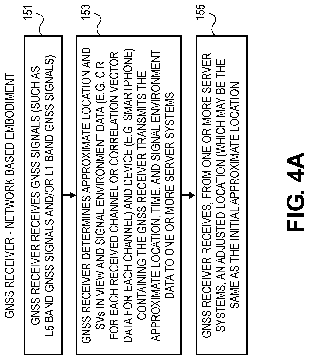
[0080]transmitting, from the network to a device near the approximate location, the set of data describing expected SV signal reception data based on the determined 3D data; and wherein the device performs the method of claim 1.


PUM


Abstract

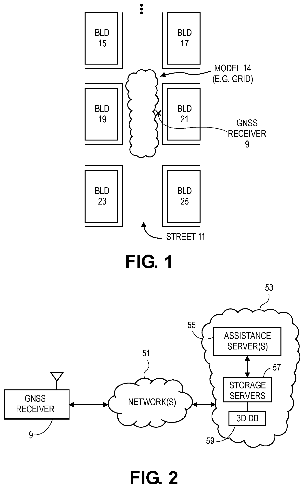
This disclosure describes methods, systems and machine readable media that can provide position solutions using, for example, pattern matching with GNSS signals in urban canyons. In one method, based upon an approximate location in an urban canyon and a set of 3D data about building structures in the urban canyon, an expected signal reception data can be generated for both line of sight and non-line of sight GNSS signals from GNSS satellites, or other sources of GNSS signals, at each point in a set of points in a grid (or other model) in the vicinity of the approximate location). This expected signal reception data can be matched to a received set of GNSS signals that have been received by a GNSS receiver, and the result of the matching can produce an adjustment to the approximate location that is used in the position solution of the GNSS receiver.

Description

[0001]This application claims the benefit of and priority to the following US provisional patent applications: U.S. provisional patent application No. 63 / 010,673, filed Apr. 15, 2020; U.S. provisional patent application No. 62 / 704,417, filed May 8, 2020; and U.S. provisional patent application No. 62 / 705,725, filed Jul. 13, 2020; and all of these provisional applications are incorporated herein by reference.BACKGROUND[0002]This disclosure relates to navigation systems, such as GNSS receivers that receive GNSS signals from GNSS satellites and use those signals to determine their position.[0003]Urban canyons present problems for GNSS receivers because the tall buildings which line the streets of cities often block direct, line of sight signals from reaching the GNSS receiver. Moreover, reflected GNSS signals, that are reflected off the buildings, can require further processing in the GNSS receiver to distinguish between line of sight (LOS) signals and non-line of sight (NLOS) signals....

Claims


Application Information

Patent Timeline
IPC IPC(8): G01S19/42G01S19/40G01S19/32
CPCG01S19/428G01S19/32G01S19/40G01S5/02521G01S5/02528
Inventor GARIN, LIONELMAAREF, MAHDISHIVARAMAIAH, NAGARAJMCBURNEY, PAULMOEGLEIN, MARKKRASNER, NORMAN
Owner ONENAV INC
Learn More