Vehicle air conditioning device

Pending Publication Date: 2021-10-07
SANDEN CORP
View PDF2 Cites 9 Cited by
  • Summary
  • Abstract
  • Description
  • Claims
  • Application Information

AI Technical Summary

Benefits of technology

The present invention relates to a vehicle air conditioning system that includes a compressor, radiator, heat absorber, outdoor heat exchanger, control device, and equipment temperature adjusting device. The system can cool or heat the inside of the vehicle cabin using the refrigerant and the heating medium. The equipment temperature adjusting device can circulate the heating medium to the battery and a predetermined object other than the battery to adjust its temperature. The control device can execute a flow passage control state to circulate the heating medium between the battery and the temperature-adjusted object, or between the battery and the air-heating medium heat exchanger, to efficiently cool or heat the inside of the cabin while avoiding frost formation on the outdoor heat exchanger. The system can also cool the battery while cooling the temperature-adjusted object, or heat both the battery and the temperature-adjusted object to maintain optimal performance under various environmental conditions.

Problems solved by technology

In addition, if the charge and discharge of the battery are performed under an environment where the temperature is high due to, for example, self-heating, there is also a risk that deterioration thereof may progress and the battery may cause an operation failure and lead to breakage in the end.

Method used


Image

  • Vehicle air conditioning device
  • Vehicle air conditioning device
  • Vehicle air conditioning device

Examples


first embodiment

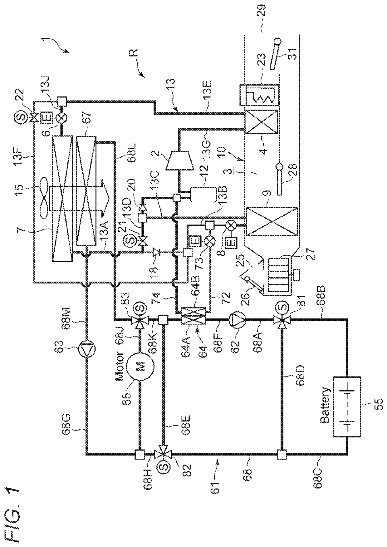
[0030]FIG. 1 is a configuration diagram of a vehicle air conditioning apparatus 1 of an embodiment to which the present invention is applied. A vehicle of the embodiment to which the present invention is applied is an electric vehicle (EV) that is equipped with no engine (internal combustion engine), but equipped with a battery 55 (e.g., a lithium battery) and driven to run by supplying, to a traveling motor (electric motor) 65, power charged in the battery 55 from an external power supply. Further, the vehicle air conditioning apparatus 1 is also driven with the power supplied from the battery 55.

[0031]That is, in the electric vehicle that is not capable of performing heating using engine waste heat, the vehicle air conditioning apparatus 1 performs a heating operation through a heat pump operation using a refrigerant circuit R, and further selectively executes air-conditioning operations including a dehumidifying and heating operation, a dehumidifying and cooling operation, and a ...

second embodiment

[0115]Next, a configuration and operation of a vehicle air conditioning apparatus 1 of another embodiment of the present invention will be described with reference to FIG. 8. The configuration of this embodiment differs from that in the case of the first embodiment (FIG. 1) only in an equipment temperature adjusting device 61, and the other part is similar to that of the first embodiment. In the equipment temperature adjusting device 61 of this embodiment, a heating medium pipe 68N is connected to the outlet of the battery 55 and also connected to an inlet of a fourth three-way valve 84 that is also the flow passage switching device. Further, the heating medium pipe 68C described above is connected to one outlet of the fourth three-way valve 84.

[0116]Further, a heating medium pipe 68R is connected to the other outlet of the fourth three-way valve 84 and also connected to a suction side of a third circulating pump 87 that is also the circulating device. A heating medium pipe 68S is c...


PUM


Abstract

To provide a vehicle air conditioning apparatus capable of smoothly performing temperature adjustment of a battery and a temperature-adjusted object other than the battery that are mounted on a vehicle. A vehicle air conditioning apparatus includes an equipment temperature adjusting device 61 for circulating a heating medium to a battery 55 and a traveling motor 65 to adjust the temperature of the battery 55 and the temperature of the traveling motor 65. The equipment temperature adjusting device includes circulating pumps 62, 63, and 87 for circulating the heating medium to the battery and the temperature-adjusted object, a refrigerant-heating medium heat exchanger 64 for exchanging heat between a refrigerant and the heating medium, an air-heating medium heat exchanger 67 for exchanging heat between outdoor air and the heating medium, and three-way valves 81 to 83 for controlling circulation of the heating medium to the battery and the traveling motor.

Description

TECHNICAL FIELD[0001]The present invention relates to a heat pump type vehicle air conditioning apparatus.BACKGROUND ART[0002]Actualization of environmental problems in recent years has resulted in widespread use of vehicles such as hybrid vehicles and electric vehicles. Such a vehicle drives a traveling motor with power supplied from a battery mounted on the vehicle. Further, as an air conditioning apparatus applicable to such a vehicle, there has been developed an air conditioning apparatus that includes a refrigerant circuit in which a compressor, a radiator, a heat absorber, and an outdoor heat exchanger are connected, and heats inside of a cabin by causing a refrigerant discharged from the compressor to dissipate heat in the radiator and causing the refrigerant that has dissipated heat in the radiator to absorb heat in the outdoor heat exchanger and cools the inside of the cabin by causing the refrigerant discharged from the compressor to dissipate heat in the outdoor heat exch...

Claims


Application Information

Patent Timeline
IPC IPC(8): B60H1/00B60H1/32
CPCB60H1/00278B60H1/3205B60H2001/00307B60H1/32281B60H1/32011B60H1/00921B60H2001/00928B60H2001/00949
Inventor ISHIZEKI, TETSUYA
Owner SANDEN CORP
Why Eureka
Try Eureka