Light-guiding optical unit for a light device of motor vehicles

a technology of light-guiding optical unit and motor vehicle, which is applied in the direction of planar/plate-like light guides, lighting and heating apparatus, instruments, etc., can solve the problems of high requirements for electronic equipment of light-guiding devices, inability to achieve a higher degree of light collimation and maximum intensities, and inefficient unbinding of light in the required direction, etc., to achieve simplified schematic vertical cross-sectional views

Active Publication Date: 2021-09-30
PO LIGHTING CZECH SRO
View PDF7 Cites 2 Cited by
  • Summary
  • Abstract
  • Description
  • Claims
  • Application Information

AI Technical Summary

Benefits of technology

The invention is a light-guiding optical unit for motor vehicles that uses a light guide with a routing surface and a prismatic structure to direct light rays from the routing surface to the output surface. The prismatic structure includes reflective surfaces that are connected by connecting surfaces, and the reflective surfaces are either not broken or broken and comprise at least two sections that are ascending or descending with respect to the top surface. The light guide may have a curved or planar plate shape, and the reflective surfaces may have the shape of arches or be broken. The technical effects of the invention include improved lighting efficiency, energy savings, and better control over the light beam.

Problems solved by technology

A common disadvantage of known light guides used for light devices of motor vehicles is the fact that light propagates through the light guide material in an uncontrolled way, which renders efficient unbinding of light in the required direction and achievement of a higher degree of light collimation and amplification of maximum intensities impossible.
This brings not only higher financial costs, but also higher requirements for the electronic equipment of the light device, and thus increased production costs of the light device.
A disadvantage of these light-guiding systems is the fact that on a total reflection, a part of the light rays is lost or sent in an undesired direction.
Another disadvantage of these systems is that high light efficiency and a uniform distribution of light intensity on the output surface cannot be achieved at the same time.
A disadvantage of this solution is that the primary optical element only lights up the collimating and prismatic structure in a narrow region.
A disadvantage of this solution is that the efficiency of the system uses the axial symmetry of the emission characteristic of the source, and especially the primary optical system is designed with respect to this.
Another disadvantage of the prior art is that the unbinding prismatic structure comprises stepwise arranged primary and secondary surface sections.
Such an arrangement has its limitations from the structural and engineering point of view and the point of view of the optical design of the lighting device.
E.g. during the production of the prismatic structure, a non-zero diameter of the production tool causes rounding of the transition in the joint between the primary and secondary section, which consequently has an impact on the size of the effective area of individual surface sections.

Method used


Image

  • Light-guiding optical unit for a light device of motor vehicles
  • Light-guiding optical unit for a light device of motor vehicles
  • Light-guiding optical unit for a light device of motor vehicles

Examples


Embodiment Construction

OF EMBODIMENTS OF THE INVENTION

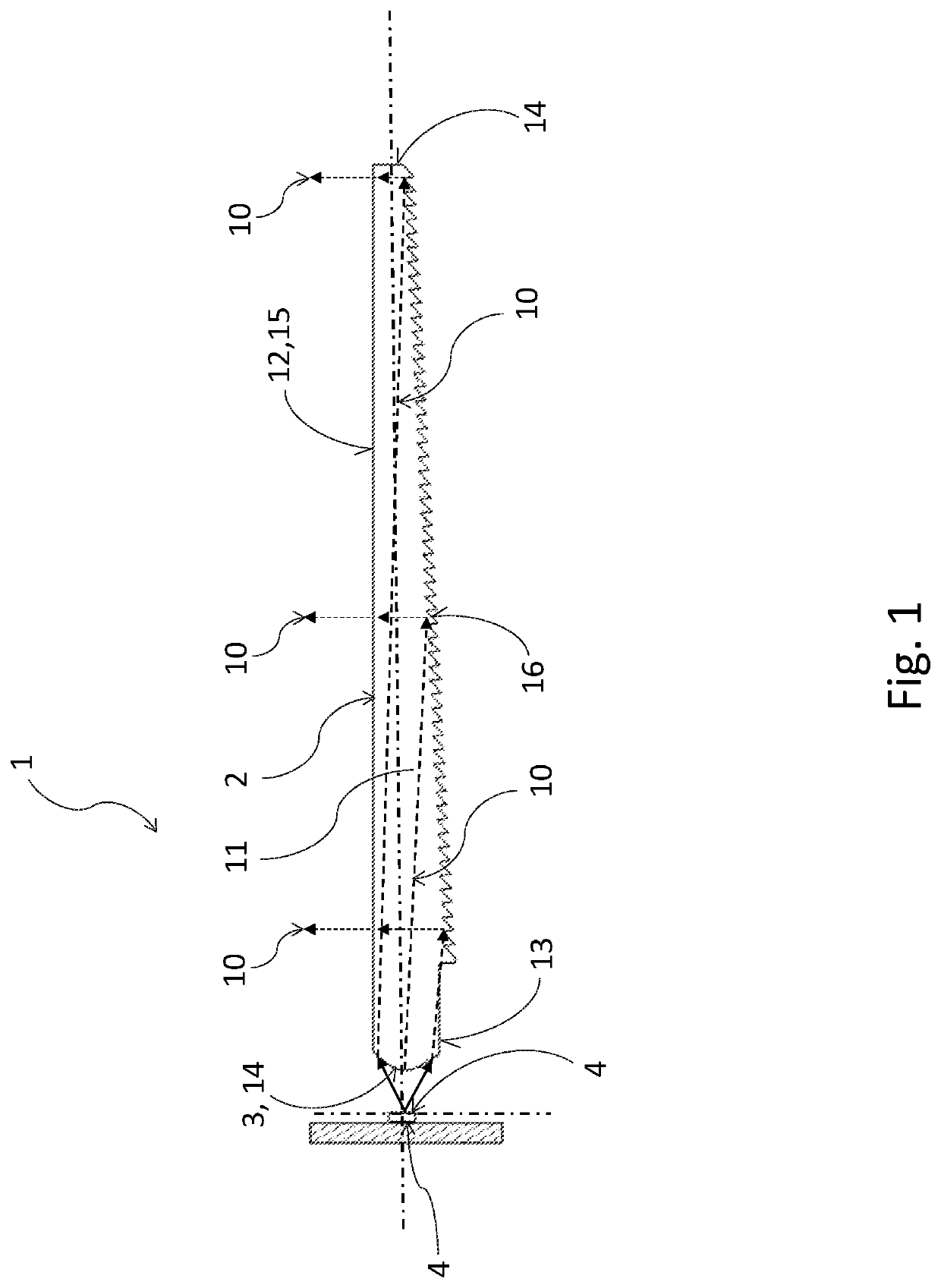
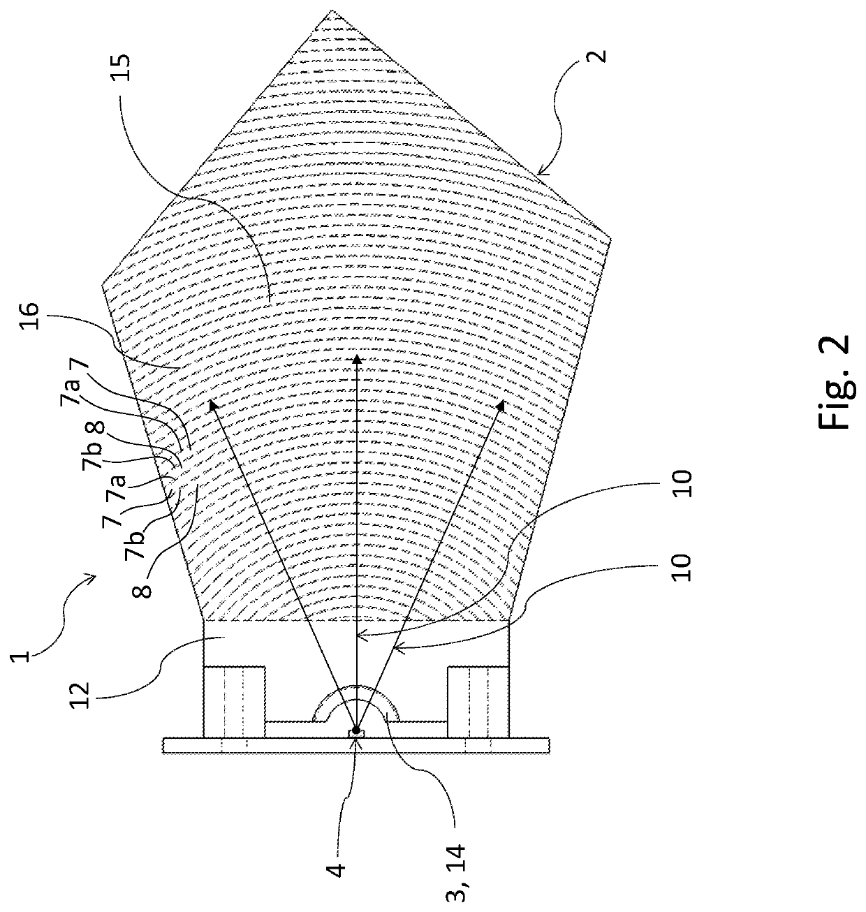
[0049]The adjectives “top” and “bottom” in the text of this application relate to the position shown in the attached drawings (except FIG. 2, showing a top view), and these adjectives do not predict or define the actual position of the light guide 2 with respect to the vehicle where the light-guiding optical unit 1 is installed in use. The adjectives “preceding” and “next” express a relative order in the propagation direction of light rays 10 from the routing surface 3 further into the light guide 2. A “vertical plane” refers to the projection plane of the figures (except FIG. 2) and a “horizontal plane” refers to a plane perpendicular to the vertical plane.

[0050]FIG. 1 and FIG. 2 show an embodiment example of a light-guiding optical unit 1 according to the present invention. The light-guiding optical unit 1 comprises a light guide 2 and a routing surface 3 of a free form—“free-form” routing surface 3. In this embodiment example, it is a refracting rou...


PUM


Abstract

The light-guiding optical unit (1) for a light device of motor vehicles comprises a light guide (2) that comprises at least one routing surface (3), and at least one light source (4) to generate light rays (10). The light-guide (2) further comprises a top surface (12) at least a part of which is constituted by the output surface (15), and a bottom surface (13) opposite the top surface (12) and fitted with a prismatic structure (16) comprising reflective surfaces (7). The routing surface (3) and the reflective surfaces (7) are mutually arranged in such a way that the routing surface (3), by means of routing by refraction on this surface (3) or reflection from this surface (3), directs light rays (10) to the prismatic structure (16) in such a way that it directly lights up only the reflective surfaces (7) with the light rays (10), the reflective surfaces (7) being configured to direct light rays (10) that have fallen onto them this way directly from the routing surface (3) to the output surface (15) in such a way that the light rays (10) can exit from the light guide (2) through the output surface (15).

Description

CROSS-REFERENCE TO RELATED APPLICATIONS[0001]This non-provisional patent application claims the priority benefit of Czech Patent Application No. PV 2020-178 entitled “A light-guiding optical unit for a light device of motor vehicles,” filed Mar. 30, 2020, the entire disclosure of which is incorporated herein by reference.FIELD OF THE INVENTION[0002]The invention relates to a light-guiding optical unit for a light device of motor vehicles comprising a light guide of a plate-like or rod-like shape to guide light emitted by the light source.BACKGROUND INFORMATION[0003]A common disadvantage of known light guides used for light devices of motor vehicles is the fact that light propagates through the light guide material in an uncontrolled way, which renders efficient unbinding of light in the required direction and achievement of a higher degree of light collimation and amplification of maximum intensities impossible.[0004]Thus, in the field of designing light guides and light guiding sys...

Claims


Application Information

Patent Timeline
Patent Type & Authority Applications(United States)
IPC IPC(8): F21S41/24F21S41/33
CPCF21S41/24F21S41/337F21V13/04G02B6/00B60Q1/00F21S43/239F21S43/245F21S43/247F21S43/315G02B6/002G02B6/0038G02B6/0046G02B6/0048G02B6/0055G02B6/0018G02B6/0068
Inventor JUHANAK, MICHALGLOSS, TOMASHRUSKA, JAKUB
Owner PO LIGHTING CZECH SRO
Why Eureka
Try Eureka