
Keypad

a keypad and keypad body technology, applied in the field of thin keypads, can solve the problems of increasing the spatial requirements of the keypad along with the other mechanical parts, increasing the complexity of the mobile device, and increasing the complexity of the mechanical parts, and reducing the thickness of the resulting keypad

Active Publication Date: 2010-03-04
NOKIA TECHNOLOGLES OY
View PDF15 Cites 209 Cited by
  • Summary
  • Abstract
  • Description
  • Claims
  • Application Information

AI Technical Summary

Benefits of technology

[0009]The combination of a capacitive sensor and a light guide allows for a very thin construction of the keypad, whilst the piezo element allows for improved determination of keystrokes by pressure sensing.
[0013]Thus, haptic feedback can be provided to the user to indicate that a keystroke has been accepted, thereby improving user confidence in a way that does not require a large thickness, like in mechanical “click” systems, and that does not require the use of irritating beeps for confirming a keystroke.
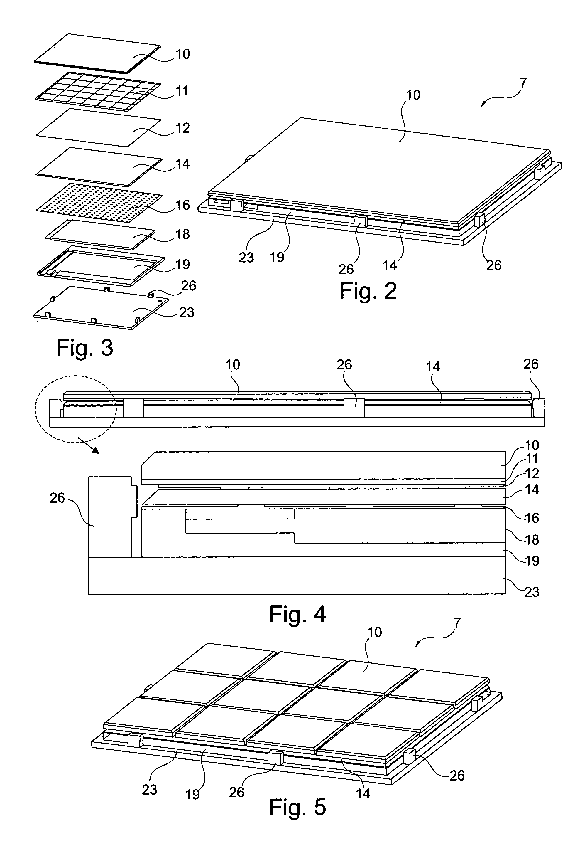
[0018]The capacitive sensor layer is sensitive to high voltage. The piezo layer uses high-voltage. By placing the electrically non-conducting light guide layer between the capacitive sensor layer and the piezo layer, the light guide layer assumes a second function, namely electrically insulating the capacitive layer from the piezo layer. By using one layer for two functions, one physical layer can be omitted form the keypad and the thickness of the resulting keypad is reduced.
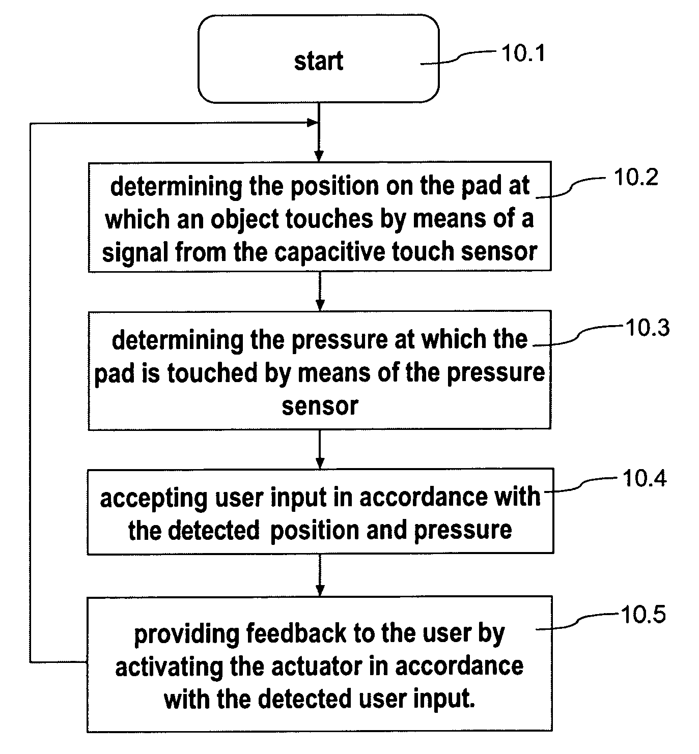
[0034]It is another object of the invention to provide a method for user input that does not have or at least reduces the drawbacks explained above. This object is achieved by providing a method for user input and feedback with a keypad or touchpad that includes a capacitive touch sensor, a pressure sensor and an actuator, the method comprising determining the position on the keypad or touch pad at which an object touches by means of a signal from the capacitive touch sensor, determining the pressure at which the keypad or touchpad is touched by means of the pressure sensor, accepting user input in accordance with the detected position and pressure, and providing feedback to the user by activating the actuator in accordance with the detected user input.

Problems solved by technology

Mobile devices become smaller and at the same time more complex.
One challenge in mobile phone user interface design is that the spatial requirements for the keypad to shrink along with the other mechanical parts.
Another challenge in mobile phone user interface design is to provide a user interface that is intuitive, easy to learn, behaves in a consistent, predictable manner and makes the best use of limited operation face surface area.
A user interface needs to provide a sufficient number of controls to manage the inherent complexity of the mobile phone whilst ensuring that there are not too many controls are options available to the user at any one time, thereby causing confusion.

Method used


Image

  • Keypad
  • Keypad
  • Keypad

Examples


Embodiment Construction

[0049]In the following detailed description, the keypad and mobile device according to the invention will be described by the preferred embodiments

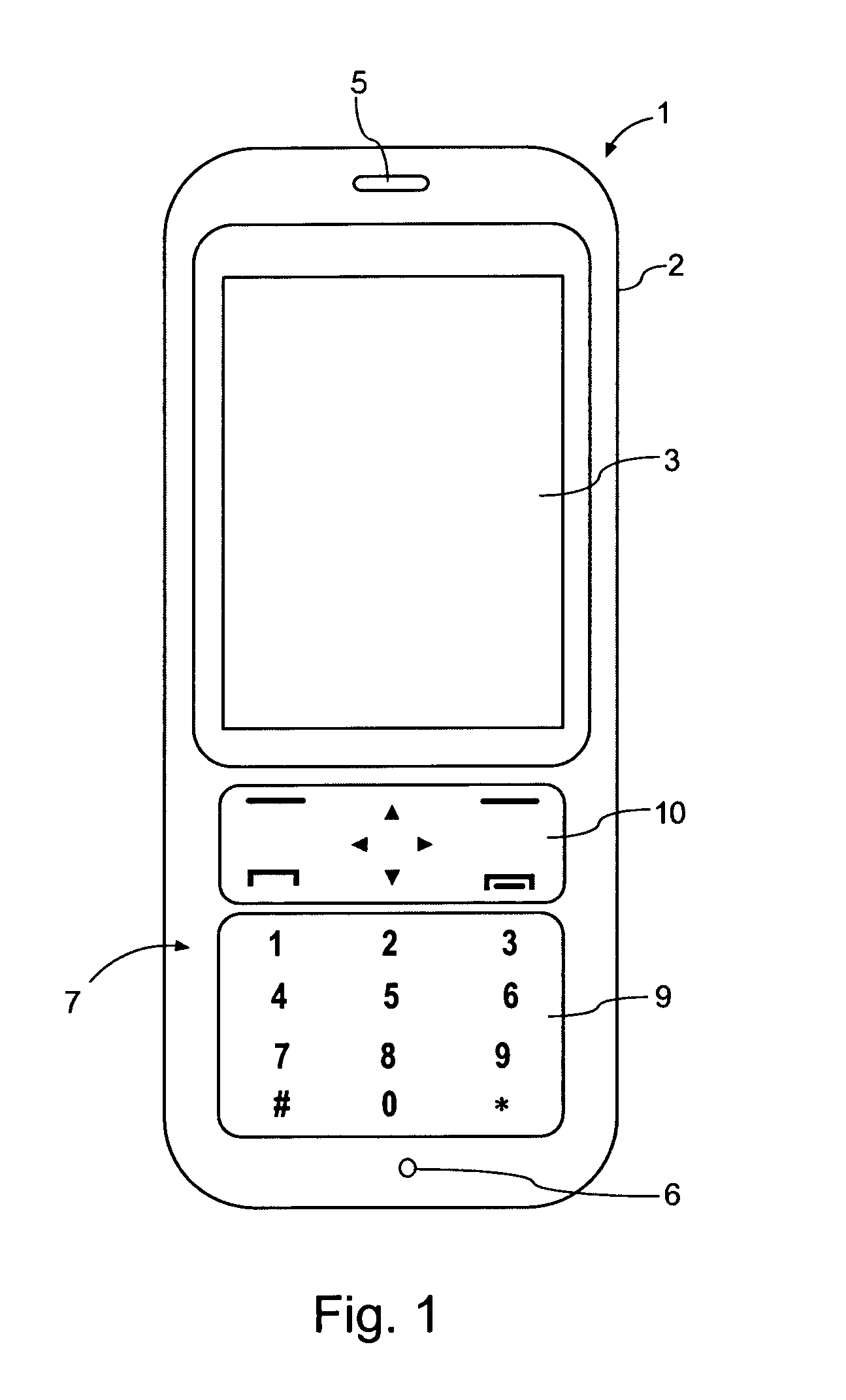
[0050]FIG. 1 illustrates a mobile device according to an embodiment of the invention in the form of a mobile phone 1. The mobile phone 1 includes a housing 2, a display 3, a speaker 5, a microphone 6 (only the opening in the housing of the speaker and the microphone can be seen in FIG. 1) and a keypad 7. The keypad includes an adaptive part 9, here shown with numerical keys and a part 10 with navigation keys and soft keys and call handling keys.

[0051]The display 3, the speaker 5, the microphone 6, and the keypad 7 are connected in a well-known manner to a processor (not shown) in the mobile phone 1.

[0052]A first embodiment of the keypad or touchpad 7 according to the invention is illustrated in FIG. 2 by an elevated view and in FIG. 4 by an exploded view. The pad includes a top mat 10 that forms the top surface layer. A capacitive sensor ...


PUM


Abstract

A thin keypad including a top surface layer, a light guide layer, a capacitive sensing layer and a piezo layer provides for touch input, pressure input and haptic feedback.

Description

FIELD OF THE INVENTION[0001]The present invention relates to a thin keypad, in particularly to a thin keypad that includes a capacitive sensor and provides haptic feedback.BACKGROUND OF THE INVENTION[0002]Mobile devices become smaller and at the same time more complex.[0003]One challenge in mobile phone user interface design is that the spatial requirements for the keypad to shrink along with the other mechanical parts. This is especially pronounced in the thickness of the parts, as the devices are driven to more slim design.[0004]Another challenge in mobile phone user interface design is to provide a user interface that is intuitive, easy to learn, behaves in a consistent, predictable manner and makes the best use of limited operation face surface area. A user interface needs to provide a sufficient number of controls to manage the inherent complexity of the mobile phone whilst ensuring that there are not too many controls are options available to the user at any one time, thereby ...

Claims


Application Information

Patent Timeline
Patent Type & Authority Applications(United States)
IPC IPC(8): G08B6/00G06F3/02G06F3/041G06F3/0488
CPCG06F3/016G06F3/04886G06F3/044G06F3/0414
Inventor LAITINEN, PAULIKAUHANEN, MIKA
Owner NOKIA TECHNOLOGLES OY
Learn More