
Turbine blade repair method using additive manufacturing

a technology of additive manufacturing and turbine blades, which is applied in the direction of process efficiency improvement, mechanical equipment, machines/engines, etc., can solve the problems of inability to realize inability to repair damaged parts, and inability to achieve the same shape and physical properties as before repair, so as to improve the performance of the turbine blade and minimize thermal impact

Active Publication Date: 2021-09-30
DOOSAN HEAVY IND & CONSTR CO LTD
View PDF0 Cites 0 Cited by
  • Summary
  • Abstract
  • Description
  • Claims
  • Application Information

AI Technical Summary

Benefits of technology

The patent text describes a method for repairing turbine blades using additive manufacturing. This method allows for easy repair of difficult-to-repair components without the need for thermal impact. The repair can be performed using a variety of materials, such as superalloys or titanium, and can improve the performance of the turbine blade by reducing stress concentration. Additionally, a secondary structure can be formed to effectively dissipate heat and minimize thermal impact on the single-crystal structure.

Problems solved by technology

Thus, damage to the turbine blades is inevitable, and damaged portions must be repaired.
Due to the characteristics of materials that are difficult to machine, it is difficult to realize the same shape and physical properties as before repair.
It is significantly difficult to machine a superalloy or Ti with the same shape as before repair in a related art machining process.
In contrast, if a material that is easy to process is used, the physical characteristics of a repair portion may be degraded than those of the peripheral portions, thereby increasing the possibility of other damage.
Further, because the material of the repair portion is different from the material before repair, the momentum of the entire turbine blade may be changed, which may adversely affect the stability and the efficiency of a gas turbine.
The thermal impact may change physical characteristics of the turbine blade and degrade the performance of a turbine engine.

Method used


Image

  • Turbine blade repair method using additive manufacturing
  • Turbine blade repair method using additive manufacturing
  • Turbine blade repair method using additive manufacturing

Examples


Embodiment Construction

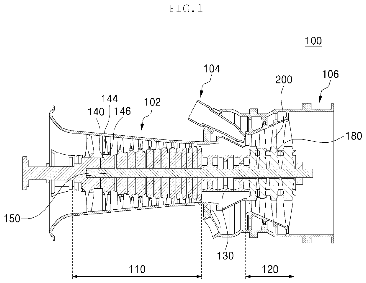
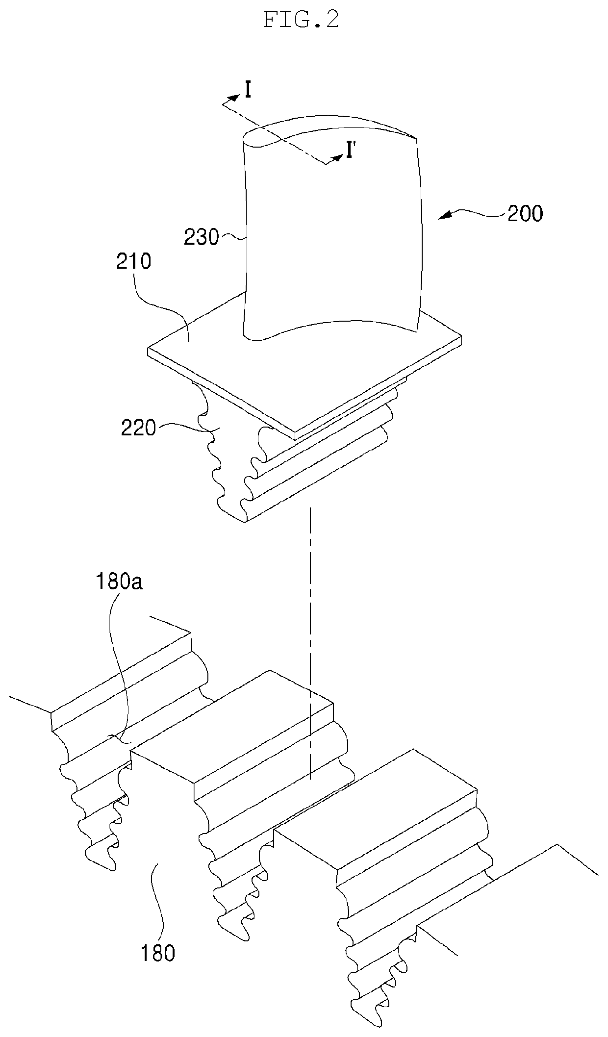
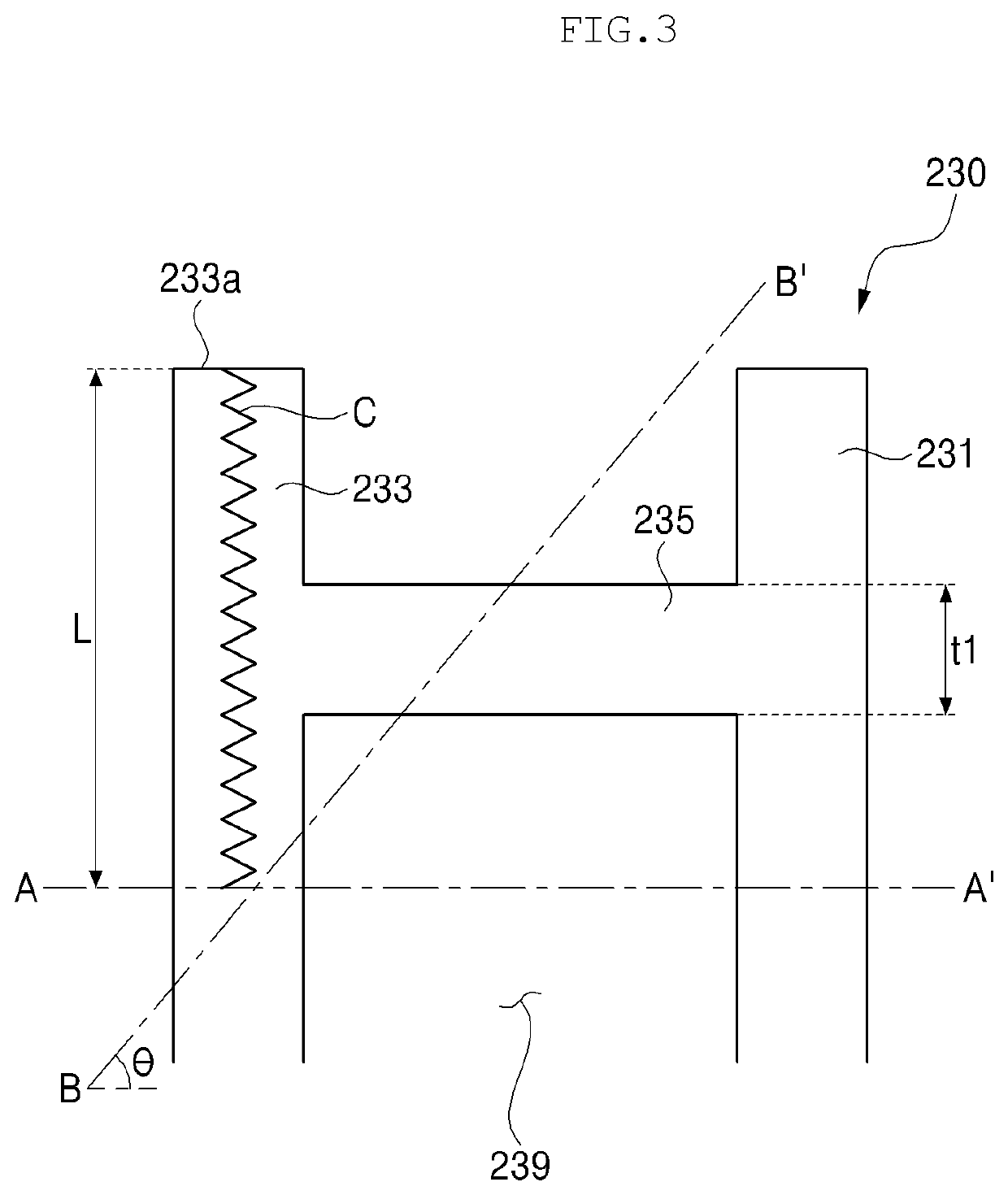
[0046]Various modifications and various embodiments will be described in detail with reference to the accompanying drawings so that those skilled in the art can easily carry out the disclosure. It should be understood, however, that the various embodiments are not for limiting the scope of the disclosure to the specific embodiment, but they should be interpreted to include all modifications, equivalents, and alternatives of the embodiments included within the spirit and scope disclosed herein.

[0047]Terms such as “first,”“second,” and so on may be used to describe a variety of components, but the components should not be limited by these terms. These terms may be merely used to distinguish one component from other components. The use of such ordinal numbers should not be construed as limiting the meaning of the term. For example, the components associated with such an ordinal number should not be limited in the order of use, placement order, or the like. If necessary, each ordinal nu...


PUM

PropertyMeasurementUnit
Widthaaaaaaaaaa
Momentumaaaaaaaaaa
Angleaaaaaaaaaa

Abstract

A turbine blade repair method is provided. The turbine blade repair method includes quantizing a position and a shape of a damaged portion of a turbine blade into numerical values, calculating a momentum loss of the turbine blade due to removal of the damaged portion, modeling a shape of a repair portion to replace the damaged portion so that the repair portion has the same momentum as the damaged portion, removing the damaged portion, and forming the modeled repair portion by performing an additive manufacturing at a position of the removed damaged portion.

Description

CROSS REFERENCE TO RELATED APPLICATIONS[0001]This application claims priority to Korean Patent Application No. 10-2020-0037317, filed on Mar. 27, 2020 and Korean Patent Application No. 10-2020-0037319, filed on Mar. 27, 2020, the disclosures of which are incorporated herein by reference in their entireties.FIELD[0002]Apparatuses and methods consistent with exemplary embodiments relate to a turbine blade repair method using additive manufacturing and, more particularly, to a method of repairing damage to a squealer of a turbine blade using additive manufacturing or stably forming a secondary structure on a single-crystal structure, such as a turbine blade, using additive manufacturing.BACKGROUND[0003]Turbine blades used in power generation equipment are key components that convert energy from a fluid such as steam or air into mechanical energy, and are continuously exposed to high-temperature fluid flow environments. Thus, damage to the turbine blades is inevitable, and damaged porti...

Claims


Application Information

Patent Timeline
IPC IPC(8): B23P6/00F02C7/00
CPCB23P6/005B23P6/007F05D2260/22141F05D2220/32F05D2230/80F02C7/00B22F7/062B33Y10/00B22F3/115B22F2007/068F01D5/005F01D5/027B33Y80/00F01D5/16F05D2230/31Y02P10/25Y10T29/49318Y10T29/49734
Inventor SHIN, YOUNG HO
Owner DOOSAN HEAVY IND & CONSTR CO LTD
Learn More