
Lockable container

a technology of lockable containers and containers, which is applied in the field of improved lockable containers, can solve the problems of more difficult to see alphanumerical indicia, more difficult to manipulate the less wide rings than the wider rings, and the process is more difficult to take longer, so as to eliminate the tapering of the cylindrical member

Active Publication Date: 2021-09-30
SECURE MEDICATION SYST
View PDF0 Cites 0 Cited by
  • Summary
  • Abstract
  • Description
  • Claims
  • Application Information

AI Technical Summary

Benefits of technology

The patent text talks about the benefits of a container that has a locking programmable feature. The text also discusses the issue of ring indexing tolerance and the tapering of the cylindrical member holding the rotatable rings. The aim of the patent is to provide a solution to these issues by providing a cylindrical member with a uniform diameter. In simpler terms, the patent is about improving the accuracy and reliability of a container's locking mechanism.

Problems solved by technology

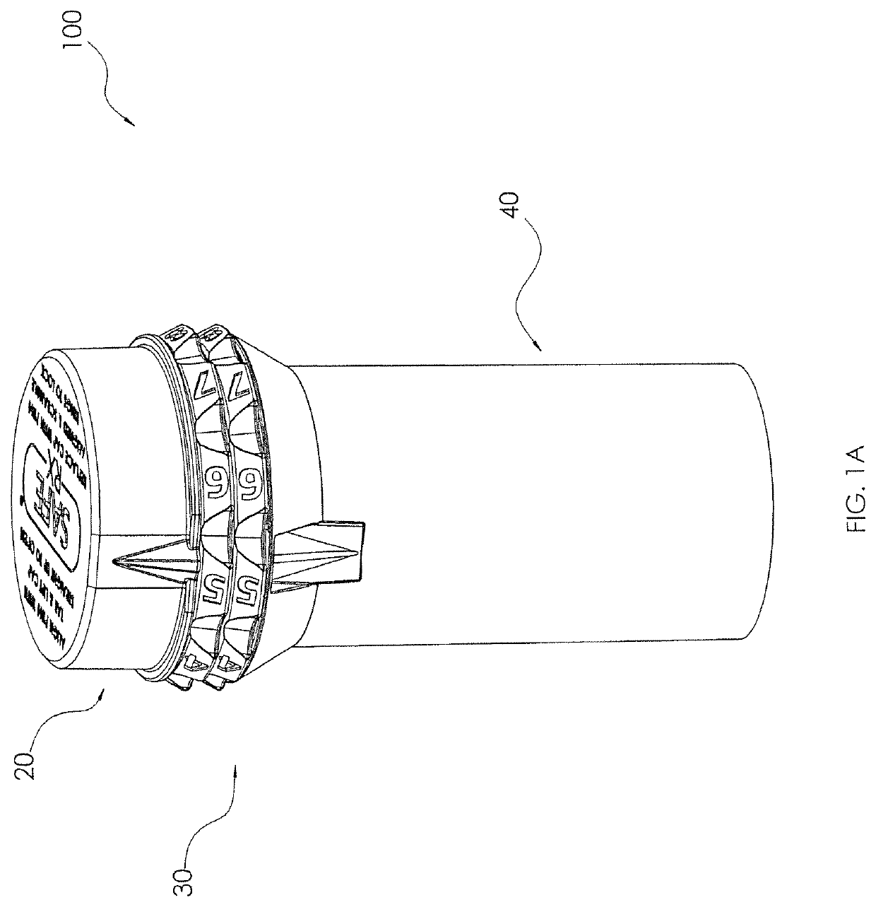
Problematically, some consumers may find it more difficult to see the alphanumerical indicia on the less wide rings than on wider rings.
These same and other consumers may also find it more difficult to manipulate the less wide rings than the wider rings.
Disadvantageously, rotating one ring may affect the alignment of adjacent rings (e.g., due to “sticky” rings), requiring the process to take longer and the rings having to be moved back and forth to provide an exact alignment.
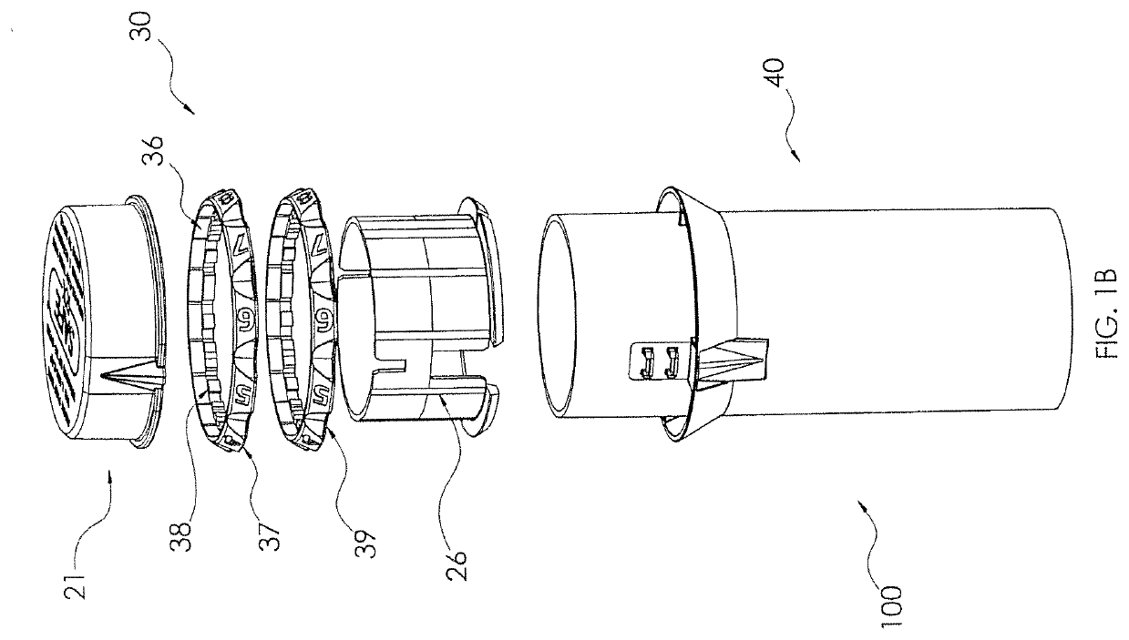
Tolerances in manufacturing of, for example, the caps, the rotatable rings, the tabs on the rings, the flanges, and the canister portion, as well as the number of rotatable rings, may make unlocking the cap and canister combination, as well as opening the container, more difficult.
Alternatively, or in addition, the relative alignment of the alphanumerical indicia on outer surface of the ring with the tabs on the inner surface of the ring during manufacture may be off sufficiently, such that, even if combination code is properly aligned along the vertical axis of the projections formed on the canister portion, one or more tabs may interfere with the projections, preventing removal of the cap from the canister portion.

Method used


Image

  • Lockable container
  • Lockable container
  • Lockable container

Examples


second embodiment

[0065]Referring to FIG. 9, an illustrative embodiment of a second element 70 for use with a first element 50 and rotatable rings 60 in connection with a locking programmable container 100′ is shown. Although the embodied second element 70 is shown as having an annular shape, this is done for illustrative purposes only. Optionally, the second element 70 may have a belled or mushroom shape. The second element 70, which in the second embodiment may function as a cap to the canister of the container 100′ may take on any practical structural or aesthetic shape. Advantageously, the annular, belled, and mushroom shapes may serve a blocking function to prevent unauthorized personnel from observing the location where the tabs to the combination code have removed.

[0066]In some embodiments, the second element 70 may include an open first end 71, a (e.g., cylindrical) sidewall 72, and a top portion 73 that includes a completely closed second end 76. Preferably, the outer diameter of the sidewal...

third embodiment

[0070]Referring to FIGS. 10A and 10B, isometric and exploded views of a locking programmable container 100″, respectively, are shown. In some embodiments, the locking programmable container 100″ may include a first element 80, a plurality of rotatable rings 90, and a second element 110. While any number of rotatable rings 90 may be used, two rings 90 are shown in the figures and are preferred. In this variation, the rotatable rings 90 may be adapted for use on the canister portion of the container 100″.

[0071]As shown in FIG. 10B, the rotatable rings 90 may be annular, having an inner surface 91 and an outer surface 92. In some implementations, a plurality of removable tabs 93 may be formed on the inner surface 91 of each ring 90, while an alphanumeric character 94 may be located on the outer surface 92 of each ring 90. The alphanumerical characters 94 enable the consumer, pharmacist, or authorized third party to create a multi-digit (e.g., a two-digit) combination code for the purpo...

first embodiment

[0089]Alternatively, the consumer, pharmacist, authorized third party, and the like may use an encoder 200 to set the combination code for a locking container 100. Referring to FIGS. 14 and 15, an illustrative first embodiment of an encoding device or encoder 200 for programming a combination code in the rotatable rings disposed on the first element of a locking container is shown. In some embodiments, the encoder 200 may include a base portion 210 and a plunger portion 220. In some implementations, the base portion 210 of the encoder 200 may be configured to include a base element 201 (e.g., to provide support and stability) to which a post portion 202 is fixedly attached (e.g., via unitary construction). In some variations, the post portion 202 may be structured and arranged to be a hollow cylinder having a first, closed end at a proximal end thereof (e.g., at the base element 201) and a second, open end 207 at a distal end thereof. In some variations, the post portion 202 may inc...


PUM


Abstract

A lockable container for securing items or objects, the container including a first element, which may include a cylindrical member and a retainer for capturing two or more rotatable rings on the cylindrical member, and a second element, which is mateable with the first element, cooperating with the rings to close an open end of the cylindrical member of the first element.

Description

FIELD OF THE INVENTION[0001]The present invention relates to an improved lockable container and, more specifically, to a lockable container having first and second mateable elements that can be manufactured in such a manner as to facilitate unlocking the container.BACKGROUND[0002]Tamper-proof or child-resistant containers, such as those used, for example, for distributing pharmaceutical medications, are widely used to restrict access to the contents. To provide greater security, especially for controlled substances, locking caps with selectively-programmable rings may be used. For example, U.S. Pat. No. 8,875,915 (“Container having a Programmable Combination Locking Cap”), issued to Secure Medication System, LLC of Fort Collins, Colo. and incorporated in its entirety herein by reference, describes a number of embodiments of containers that include individually programmable combination locking caps. In some embodiments, the locking cap includes a number of rotatable rings that may be...

Claims


Application Information

Patent Timeline
Patent Type & Authority Applications(United States)
IPC IPC(8): A61J1/03B65D55/14E05B37/02
CPCA61J1/03B65D55/14E05Y2900/602E05B37/02B65D55/145A61J1/1437A61J7/0046A61J1/1412E05Y2999/00
Inventor COHEN, MILTONHART, KEIRESTOQUE, DANIEL
Owner SECURE MEDICATION SYST
Learn More