Container handling vehicle with first and second sections and lifting device motor in second section

a technology of lifting device and container, which is applied in the direction of conveyors, transportation and packaging, storage devices, etc., can solve the problems of robots being more unstable than single cell robots, robots tilting excessively, and single cell robots not having any available space for larger hub motors. , the cost of bldc cards is quite high, and the overall cost of the container handling vehicle can be reduced.

Active Publication Date: 2021-09-23
AUTOSTORE TECH AS
View PDF0 Cites 0 Cited by
  • Summary
  • Abstract
  • Description
  • Claims
  • Application Information

AI Technical Summary

Benefits of technology

[0034]The lifting device may comprise a lifting shaft which comprise a first end section and a second end section for connecting a first pair of lifting bands and a second pair of lifting bands. All lifting bands may be connected to a lifting frame of the lifting device for lifting and lowering of the lifting device. The lifting bands may have a first end and a second end connected to the lifting shaft and a corresponding lifting band connector on the lifting frame, respectively. Each pair of lifting bands may have a first lifting band connected at the first end section of the lifting shaft and a second lifting band connected at the second end section of the lifting shaft. The first pair of lifting bands may extend in a substantially horizontal direction from the lifting shaft towards a band guiding assembly, the band guiding assembly may be arranged to change the direction of the first pair of lifting bands to extend in a vertical direction, and the second pair of lifting bands may extend in a vertical direction from the lifting shaft. Such setup, i.e. only one lifting shaft where all lifting bands are spooled onto, eliminates the need of a separate belt for synchronizing two independent lifting shafts.
[0043]If the lifting device motor is angled sideways, i.e. with a longitudinal axis of the lifting device motor in a horizontal or mainly horizontal direction, this has particular advantages in that as the motor may weigh up to 10 kilograms and above and may be arranged at a relatively high elevation compared to a total height of container handling vehicle, orienting the lifting device motor and angled transmission sideways provides for a more stable container handling vehicle in that the weight is more optimally distributed towards the midline of the container handling vehicle. In addition, as the control system and power source for the lifting device motor is arranged mainly in the center of an upper part of the container handling vehicle, this orientation of the lifting device motor requires shorter power cable(s) and encoder cable(s) to the control system which is advantageous as the performance is increased and the noise is significantly reduced.
[0044]The lifting device motor may be angled downwards, i.e. with a longitudinal axis of the lifting device motor in a vertical or mainly vertical direction. Such a setup renders possible the use of two lifting device motors connected to respective lifting axles. If two lifting device motors are arranged at opposite sides in the second section this can provide a more stable container handling vehicle as the weight distribution from the lifting device motors will be more advantageous in terms of the overall centre of gravity for the container handling vehicle.
[0090]The second section makes it possible to utilize larger and stronger hub motors for driving at least some of the wheels than what is possible in the prior art single cell robots, for example lifting device motors with at least 70% more axial depth and stronger e.g. at least 10% stronger lifting device motors.
[0092]The cost of BLDC cards is quite high. However, as the distance between the motors can be substantially reduced by arranging the motors in the second section, the overall cost for the container handling vehicle can be reduced because fewer BLDC cards (e.g. only one BLDC card) is required.

Problems solved by technology

The cantilever robots may have available space for larger motors, however the robots may be more unstable than their single cell counterparts.
Thus, larger motors with increased acceleration could result in the robots tilting excessively.
Thus, the prior art single cell robots do not have any available space for larger hub motors without impinging on the storage container space inside the robot.
Consequently, the prior art solutions may have potential drawbacks in relation to stability of the robots and or limited space for larger, more powerful wheel motors, in particular for single cell robots, where motors can be of the so called in-wheel-motor configuration in order to be as small as possible to fit in the wheel and vehicle body while not occupying the cavity for receiving storage containers.

Method used


Image

  • Container handling vehicle with first and second sections and lifting device motor in second section
  • Container handling vehicle with first and second sections and lifting device motor in second section
  • Container handling vehicle with first and second sections and lifting device motor in second section

Examples


Embodiment Construction

"d_n">[0130]In the following, embodiments of the invention will be discussed in more detail by way of example only and with reference to the appended drawings. It should be understood, however, that the drawings are not intended to limit the invention to the subject-matter depicted in the drawings and that features described in one drawing are not necessarily dependent on the presence of other features shown in the same drawing but can be combined with features from embodiments of other drawings.

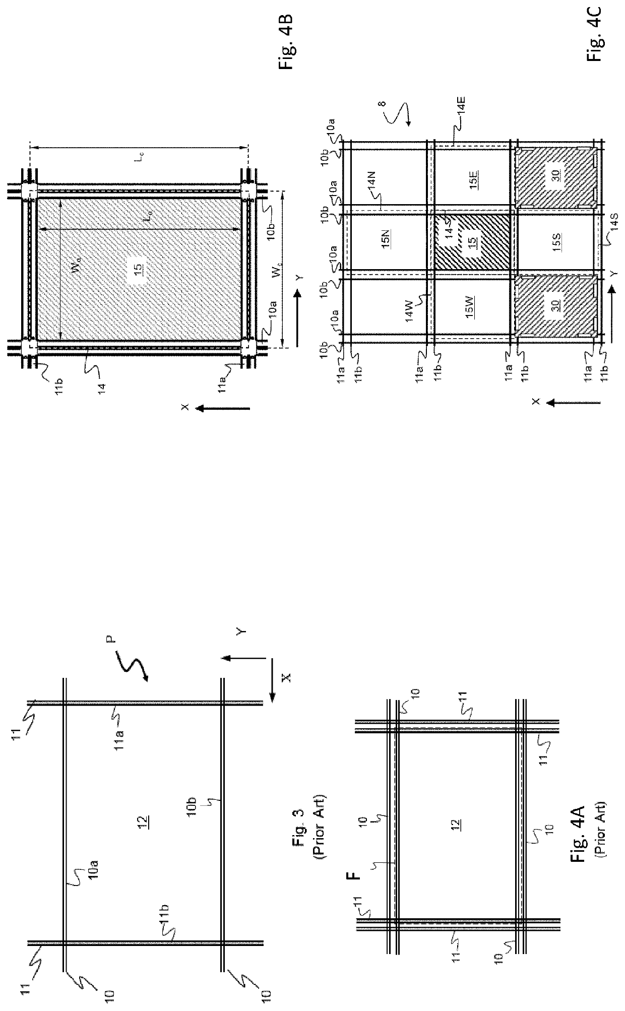
[0131]Referring to FIGS. 3 to 4C, top views of two different rail systems of the automated storage and retrieval systems are shown.

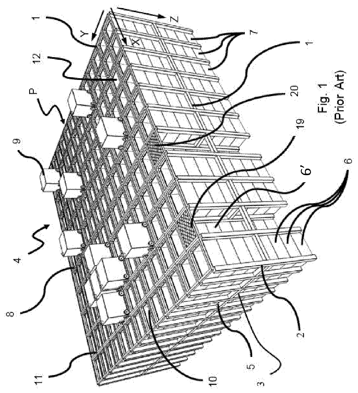
[0132]The rail system forms a grid structure or grid pattern in the horizontal plane P, see FIG. 1. The grid 4 comprises a plurality of rectangular and uniform grid locations or grid cells 14 (see FIG. 4B), where each grid cell 14 comprises a grid opening 15 (i.e. the upper end of a storage column 12) which is delimited by a pair of opposed rails 10a, 10b of a fi...


PUM


Abstract

A container handling vehicle for picking up storage containers from a three-dimensional grid of an underlying storage system includes a first set of wheels for moving the vehicle along an X direction on a rail system of the grid; and a second set of wheels for moving the vehicle along a Y direction on the rail system of the grid. The Y direction is perpendicular to the X direction. The container handling vehicle includes a vehicle body having a vehicle body footprint defined by horizontal peripheries in the X and Y directions of the vehicle body. The vehicle body includes a first section and a second section. The first section has a first footprint and the second section has a second footprint. The first and second footprints are defined by horizontal peripheries in the X and Y directions of the first and second sections respectively. The container handling vehicle includes a lifting device for lifting storage containers from the storage system; and a lifting device motor arranged to drive the lifting device when lifting storage containers from the storage system. The first section and the second section are arranged side-by-side such that a total area of the first and second footprints equals a total area of the vehicle body footprint, and a centre point of the first footprint is arranged off centre relative a centre point of the vehicle body footprint. The first section defines a storage container receiving space which is configured to accommodate a storage container. The first section also accommodates the lifting device for lifting a storage container from the storage system. The lifting device motor is accommodated in the second section.

Description

[0001]The present invention relates to the field container handling vehicles for automated storage and retrieval systems and to automated storage and retrieval systems comprising such container handling vehicles.BACKGROUND[0002]The Applicant's already known AutoStore system is a storage system comprising a three-dimensional storage grid structure wherein storage containers / containers are stacked on top of each other to a certain height. Such a prior art system is shown in FIG. 1. The storage system is disclosed in detail in for instance NO317366 and WO 2014 / 090684 A1.[0003]FIG. 1 discloses a framework structure of a typical prior art automated storage and retrieval system 1 and FIGS. 2a and 2b disclose known container handling vehicles of such a system.[0004]The framework structure comprises a plurality of upright members / profiles 2 and a plurality of horizontal members 3, which are supported by the upright members 2. The members 2, 3 may typically be made of metal, e.g. extruded al...

Claims


Application Information

Patent Timeline
Patent Type & Authority Applications(United States)
IPC IPC(8): B65G1/04B65G1/137
CPCB65G1/0464B65G2201/0235B65G1/137B65G1/04B65G1/0478B65G1/065
Inventor AUSTRHEIM, TROND
Owner AUTOSTORE TECH AS
Why Eureka
Try Eureka