Eureka AIR delivers breakthrough ideas for toughest innovation challenges, trusted by R&D personnel around the world.

Single-row electrical wire structure

a single-row, electrical wire technology, applied in the direction of cross-talk/noise/interference reduction, fixed connection, coupling device connection, etc., can solve the problems of small size of electronic devices, small internal space of electronic devices, and small so as to prevent emi/rfi problems, reduce the amount of used materials for wire assemblies, and improve crosstalk interference

Active Publication Date: 2021-09-16
ADVANCED CONNECTEK INC
View PDF2 Cites 1 Cited by
  • Summary
  • Abstract
  • Description
  • Claims
  • Application Information

AI Technical Summary

Benefits of technology

The patent text describes a solution to the problem of electromagnetic interference (EMI) and radiofrequency interference (RFI) for high-speed signal transmissions using flat cable structures and single-row electrical wire structures. By eliminating ground wires and increasing the spacing between signal pairs, the single-row electrical wire structure reduces the amount of material used and improves crosstalk interference. The reduced height of the single-row electrical wire structure also makes it more portable. Grounding sheets provide conduction and grounding effects and are held at the ends of the wire assembly to provide better contact with the circuit board. Overall, the patent text offers a solution to prevent EMI and RFI issues and improve the performance of high-speed signal transmissions.

Problems solved by technology

Consumer electronics tend to become smaller, thinner, and lighter.
For an electronic device (e.g., a notebook computer), the size of the electronic device is small, and the electronic device has a relatively limited internal space.

Method used


Image

  • Single-row electrical wire structure
  • Single-row electrical wire structure
  • Single-row electrical wire structure

Examples


Embodiment Construction

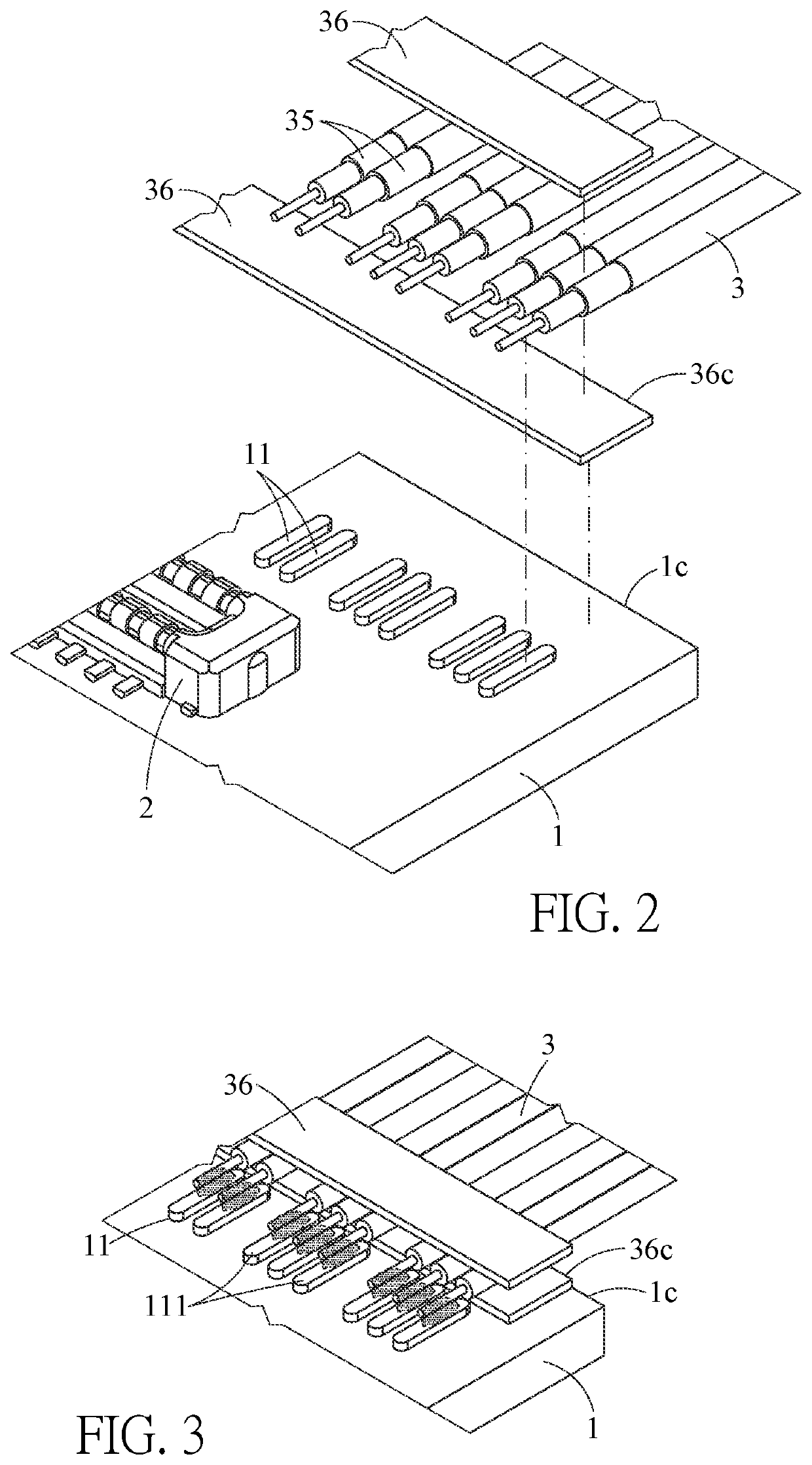
[0043]Please refer to FIGS. 1 to 6. A single-row electrical wire structure according to a first embodiment of the instant disclosure is illustrated. FIG. 1 illustrates a perspective view of a single-row electrical wire structure according to the first embodiment. FIG. 2 illustrates an exploded view of the single-row electrical wire structure of the first embodiment. FIG. 3 illustrates a schematic perspective view showing the single-row electrical wire structure of the first embodiment is to be welded. FIG. 4 illustrates a top view of the single-row electrical wire structure of the first embodiment. FIG. 5 illustrates an enlarged partial view (1) of FIG. 4. FIG. 6 illustrates an enlarged partial view (2) of FIG. 4. In this embodiment, the single-row electrical wire structure comprises a first circuit board 1, a wire assembly 3, and a second circuit board 6.

[0044]In this embodiment, a board-to-board connector 2 is on the first circuit board 1. The first circuit board 1 comprises a fir...


PUM


Abstract

A single-row electrical wire structure includes a first circuit board and a wire assembly. A board-to-board connector is on the first circuit board. The first circuit board includes a first group of contacts arranged into a single row. A distance between center portions of adjacent two contacts of the first group of contacts forms a width. The wires assembly includes a plurality of high-speed signal pairs and at least one low-speed signal pair respectively connected to the first group of contacts. A first spacing between a contact in the first group of contacts corresponding to a first high-speed signal pair of the high-speed signal pairs and a contact in the first group of contacts corresponding to a second high-speed signal pair of the high-speed signal pairs adjacent to the first high-speed signal pair is at least equal to or greater than 2 times of the width.

Description

CROSS-REFERENCE TO RELATED APPLICATION[0001]This non-provisional application claims priority under 35 U.S.C. § 119(a) to Patent Application No. 109202864 filed in Taiwan, R.O.C. on Mar. 12, 2020, the entire contents of which are hereby incorporated by reference.FIELD OF THE INVENTION[0002]The instant disclosure relates to an electrical wire structure, and more particular to a single-row electrical wire structure.BACKGROUND[0003]Consumer electronics tend to become smaller, thinner, and lighter. The electrical connection between the circuit boards with electrical wires is a common configuration in the consumer electronics. Hence, the layout of the first circuit board can be extended through the electrical wires, so that the internal space of the consumer electronics can be properly arranged. For an electronic device (e.g., a notebook computer), the size of the electronic device is small, and the electronic device has a relatively limited internal space. Therefore, the circuit boards a...

Claims


Application Information

Patent Timeline
Patent Type & Authority Applications(United States)
IPC IPC(8): H01R12/73H01R12/53H01R12/72
CPCH01R12/732H01R12/725H01R12/727H01R12/53H01R13/6461H01R13/648H01R31/06H01R12/62H01R12/596H01R12/598H05K2201/10356H05K1/117H05K2201/094H05K1/0215
Inventor WANG, WEN-YULI, TZU-HAO
Owner ADVANCED CONNECTEK INC
Why Eureka
Eureka Blog
Learn More