Coil device
a coil device and coil technology, applied in the direction of transformer/inductance details, inductance, electrical equipment, etc., can solve the problems of low inductance value and inability to obtain good inductance characteristics reduce magnetic coupling, and achieve good inductance characteristics
- Summary
- Abstract
- Description
- Claims
- Application Information
AI Technical Summary
Benefits of technology
Problems solved by technology
Method used
Image
Examples
first embodiment
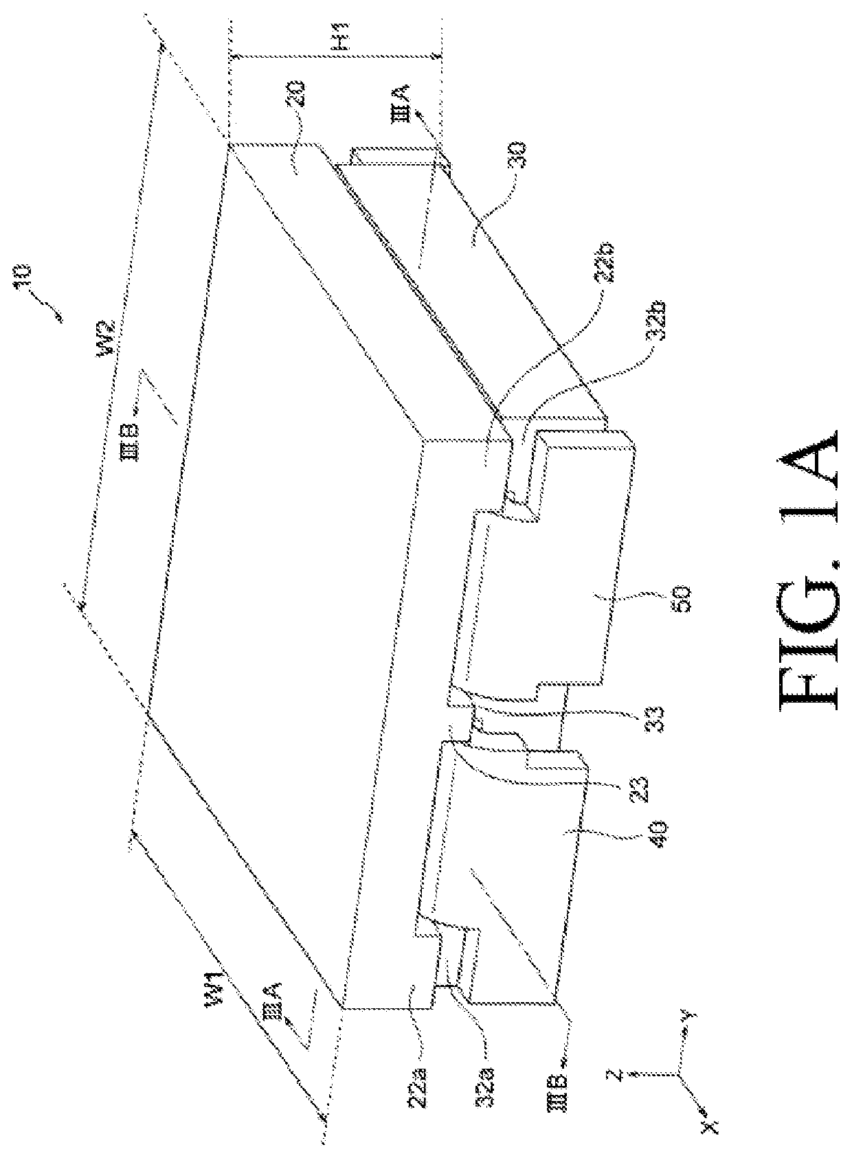
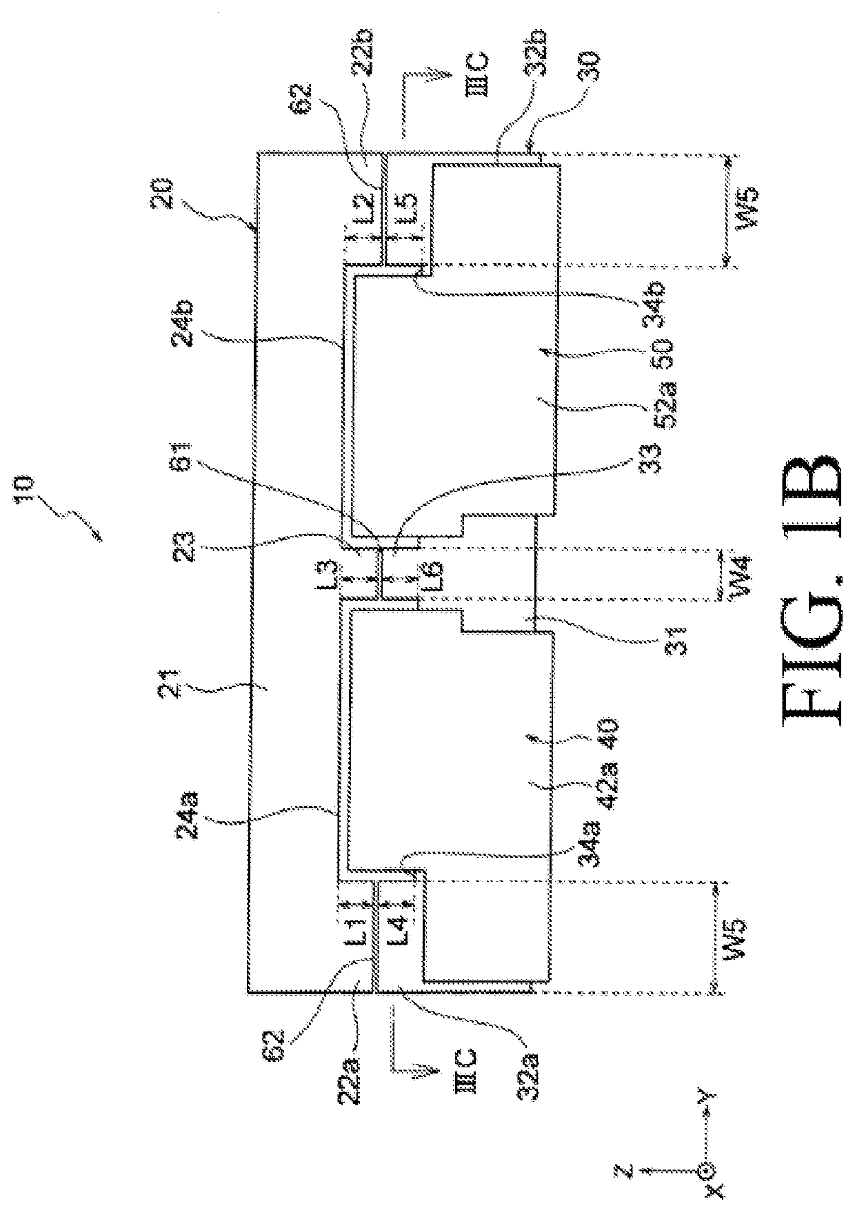
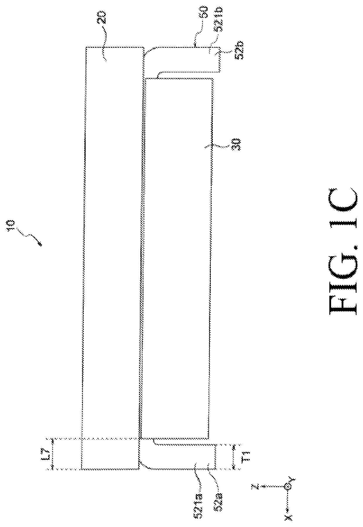
[0030]As shown in FIG. 1A, a coil device 10 according to a first embodiment of the present invention includes a first core 20, a second core 30 combined with the first core 20, and a first conductor 40 and a second conductor 50 arranged adjacent to each other between the first core 20 and the second core 30. The coil device 10 is, for example, a coupled inductor and is used as a smoothing coil for a switching power supply such as a DC / DC converter. The above-mentioned switching power supply is used in a power supply circuit in a server, a mobile terminal, or the like.
[0031]The coil device 10 has a substantially rectangular parallelepiped shape as a whole. A correlation among a width W1 in an X-axis direction of the coil device 10 (corresponding to a width in the X-axis direction of the first core 20), a width W2 in a Y-axis direction of the coil device 10, and a height H1 of the coil device 10 is W2>W1>H1. That is, an overall shape of the coil device 10 is a substantially flat shape...
second embodiment
[0079]A coil device 110 according to a second embodiment shown in FIG. 4 has the same configuration as that of the coil device 10 according to the first embodiment except for the following points, and exhibits the same effects. In FIG. 4, members common to members in the coil device 10 according to the first embodiment are denoted by common reference numerals, and a part of description thereof will be omitted.
[0080]As shown in FIG. 4, the coil device 110 includes a first core 120 and a second core 130. The first core 120 has a substantially flat plate shape (substantially rectangular parallelepiped shape) and constitutes a so-called I-shaped core.
[0081]The second core 130 includes second outer leg portions 132a, 132b, a second center leg portion 133, and second recess portions 134a, 134b. A length in the Z-axis direction of the second outer leg portions 132a, 132b is larger than the length in the Z-axis direction of the second outer leg portions 32a, 32b according to the first embod...
third embodiment
[0085]A coil device 210 according to a third embodiment shown in FIG. 5 has the same configuration as that of the coil device 10 according to the first embodiment except for the following points, and exhibits the same effects. In FIG. 5, members common to members in the coil device 10 according to the first embodiment are denoted by common reference numerals, and a part of description thereof will be omitted.
[0086]As shown in FIG. 5, the coil device 210 includes a second core 230. The second core 230 differs from the second core 30 according to the first embodiment in that the second core 230 includes a protruding portion 35. The protruding portion 35 protrudes in an X-axis direction from a side surface on one end side in the X-axis direction of the second core 230 toward outside of the second core 230. Although not shown, a protruding portion protruding in the X-axis direction toward the outside of the second core 230 is also formed on a side surface on the other end side in the X-...
PUM
| Property | Measurement | Unit |
|---|---|---|
| width W1 | aaaaa | aaaaa |
| width W2 | aaaaa | aaaaa |
| height H1 | aaaaa | aaaaa |
Abstract
Description
Claims
Application Information
 - R&D
- Intellectual Property
- Life Sciences
- Materials
- Tech Scout
- Unparalleled Data Quality
- Higher Quality Content
- 60% Fewer Hallucinations
Browse by: Latest US Patents, China's latest patents, Technical Efficacy Thesaurus, Application Domain, Technology Topic, Popular Technical Reports.
© 2025 PatSnap. All rights reserved.Legal|Privacy policy|Modern Slavery Act Transparency Statement|Sitemap|About US| Contact US: help@patsnap.com


