
A nose clamp

a nose clamp and clamping technology, applied in the field of nose clamps, can solve the problems of complex closure mechanism, inability to self-hold, and current nose compressing devices are typically complex, so as to stop a nosebleed, promote blood clotting, and control inflammation and swelling

Pending Publication Date: 2021-09-02
MINKS WENDY
View PDF2 Cites 2 Cited by
  • Summary
  • Abstract
  • Description
  • Claims
  • Application Information

AI Technical Summary

Benefits of technology

The invention is a device that uses a compressing force to hold a temperature-changing body in contact with the user's nasal sidewalls, providing a cooling or heating effect. The device also helps control inflammation and swelling and promotes clotting to stop bleeding. The temperature-changing body is placed within the jaws of the device and acts on the nasal sidewalls to provide a soothing effect.

Problems solved by technology

However, current nose compressing devices are typically complex and comprise multiple parts.
They are not self-holding and include complicated closure mechanisms that require manual adjustment to fit the nose.
These manually adjustable closure mechanisms allow for user error and can lead to under tightening or over-tightening.
The closure mechanisms can also increase the overall size, weight and cost of the devices.
It has been found that the compressing effect provided by some devices is limited and has little beneficial effect.
Certain other devices provide a pointed compressing effect over a limited surface area of the nose, and this prolonged point compression can lead to point necrosis damaging tissues in the nose.

Method used


Image

  • A nose clamp
  • A nose clamp
  • A nose clamp

Examples


first embodiment

[0058]In the clamping body depicted in FIGS. 3 to 8, the bridge (10) comprises a central region (101), first haunch region (102) and second haunch region (103) wherein the first and second haunch regions curve inwardly from the central region. The inward curve of the first and second haunch regions may range from 140° to 180°.

second embodiment

[0059]In the clamping body depicted in FIGS. 9 & 10, the bridge (10′) comprises a central region (101′), first haunch region (102′) and second haunch region (103′) wherein the first and second haunch regions curve downwardly from the central region. The downward curve of the first and second haunch regions may range from 60° to 90°.

[0060]To enhance the overall resilience of the clamping body and thereby the clamping effect, the jaws of the clamping body are double walled jaws. The first jaw comprises a first outer wall, a first inner wall and a first folding joint between the first outer wall and first inner wall. The second jaw comprises a second outer wall, a second inner wall and a second folding joint between the second outer wall and second inner wall. The folding joints are arranged between the lower ends of the outer walls and inner walls of the jaws. The inner walls are inwardly folded at the folding joints from the respective outer walls such they form a ‘return wing’ exten...


PUM


Abstract

The invention relates to a nose clamp, method of mounting the nose clamp and kit of parts to form the nose clamp. The nose clamp comprises a resilient clamping body and a temperature altering body to provide a compressing and temperature altering effect on a user's nose. The clamping body comprises a bridge to extend over a dorsum of the user's nose, and a first jaw and a second jaw to extend from the bridge along respective nasal sidewalls of the user's nose so as to apply a compressing force to compress the nasal sidewalls of the user's nose and urge the temperature altering body into contact with the nasal sidewalls. Each jaw comprises an outer wall, an inner wall, and a folding joint between the outer wall and the inner wall to fold the inner wall inwardly from the outer wall.

Description

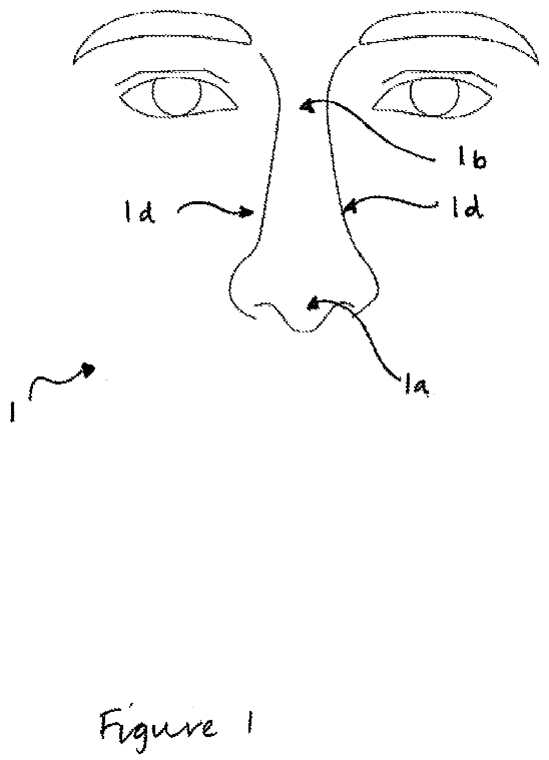
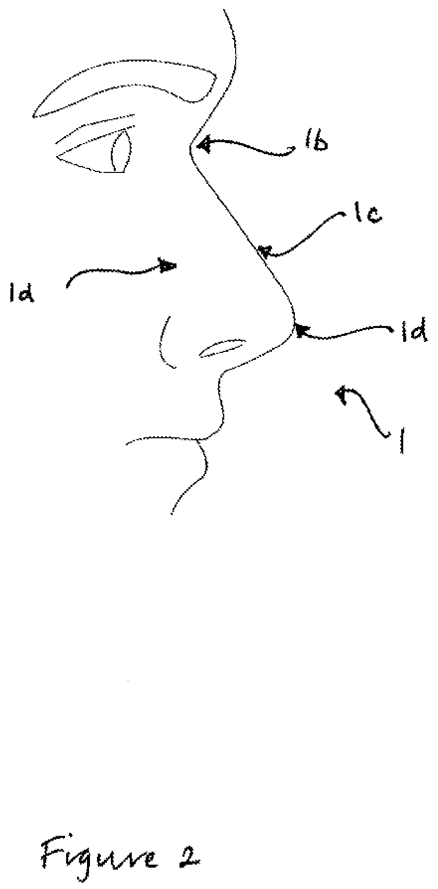
FIELD OF THE INVENTION[0001]The present invention relates to a nose clamp. In particular, the present invention relates to a nose clamp to provide a compressing and temperature altering effect on a nose.BACKGROUND OF THE INVENTION[0002]Referring to FIGS. 1 and 2, a human nose 1 is shown. The human nose 1 comprises a tip (1a) located at the end of the nose and a bridge (1b) at the top of the nose between the eye sockets. A dorsum (1c) extends between the tip and the bridge. Nasal sidewalls (1d) are cartilaginous portions arranged on either side of the dorsum, anterior to the nasal bone.[0003]It is known that compression, cooling and / or heating can provide a supporting and soothing effect to an injured nose. The compression, cooling and / or heating can also help to control inflammation and swelling of the injured nose.[0004]Nosebleeds typically occur in an anteroinferior part of the nasal septum, medial to the nasal sidewalls (sometimes referred to as the Kiesselbach's plexus or in Lit...

Claims


Application Information

Patent Timeline
Patent Type & Authority Applications(United States)
IPC IPC(8): A61B17/24A61B17/122A61F7/02
CPCA61B17/24A61B2017/12004A61F7/02A61B17/122A61F7/10A61F2007/0006A61B17/08A61B2017/00862A61F2007/0225
Inventor MINKS, WENDY
Owner MINKS WENDY
Learn More