Underwater detector, instrument and method for measuring velocity and direction of groundwater
a detection device and groundwater technology, applied in the direction of fluid speed measurement, speed/acceleration/shock measurement, instruments, etc., can solve the problems of low measurement accuracy, large operational constraints, and existing methods for measuring the velocity and direction of groundwater flow, and achieve wide application range, simple principles, and high sensitivity and accuracy.
- Summary
- Abstract
- Description
- Claims
- Application Information
AI Technical Summary
Benefits of technology
Problems solved by technology
Method used
Image

Examples
embodiment i
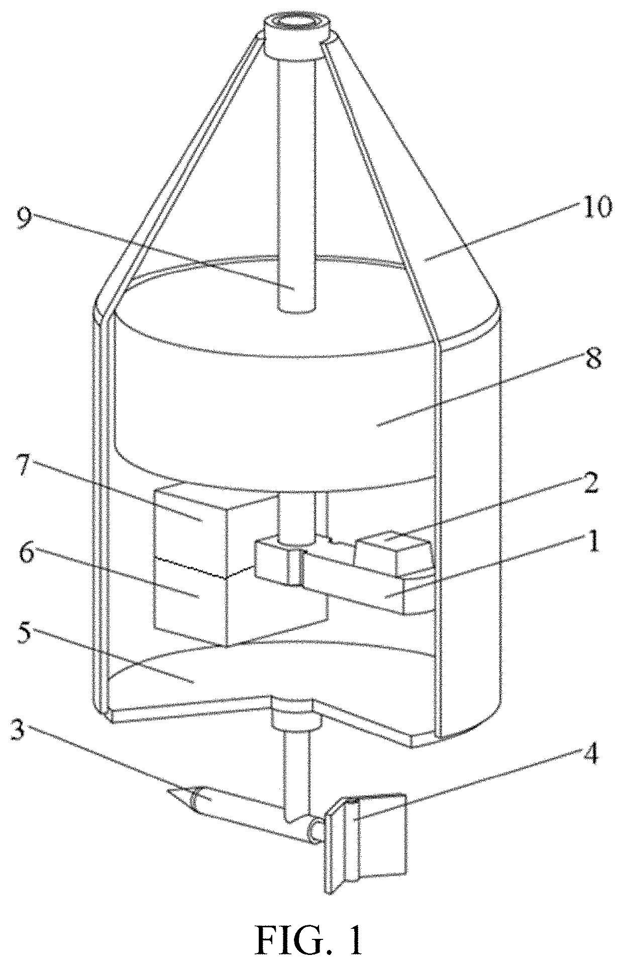
[0033]As shown in FIG. 1, an underwater detector of this embodiment includes:
[0034]a sealed enclosure 10, inside which a spindle 9, an infrared sensor module 1, and a processor module 7 are disposed, where the infrared sensor module 1 is capable of rotating around the spindle 9 at a fixed angular velocity along a horizontal plane; an electronic compass 2 is disposed on the infrared sensor module 1; and a bottom of the sealed enclosure 10 is connected to an indicator 3 through a rotary shaft, and the indicator 3 is capable of freely rotating around the rotary shaft on the horizontal plane under the action of a water flow;
[0035]the indicator 3 includes a head and a tail fin, a light source 4 configured to emit a light beam vertically upwards is disposed on the tail fin, and the light beam can be received by the infrared sensor module 1; the infrared sensor module 1 is configured to trigger the electronic compass 2 to work when receiving the light beam, and the electronic compass 2 is ...
embodiment ii
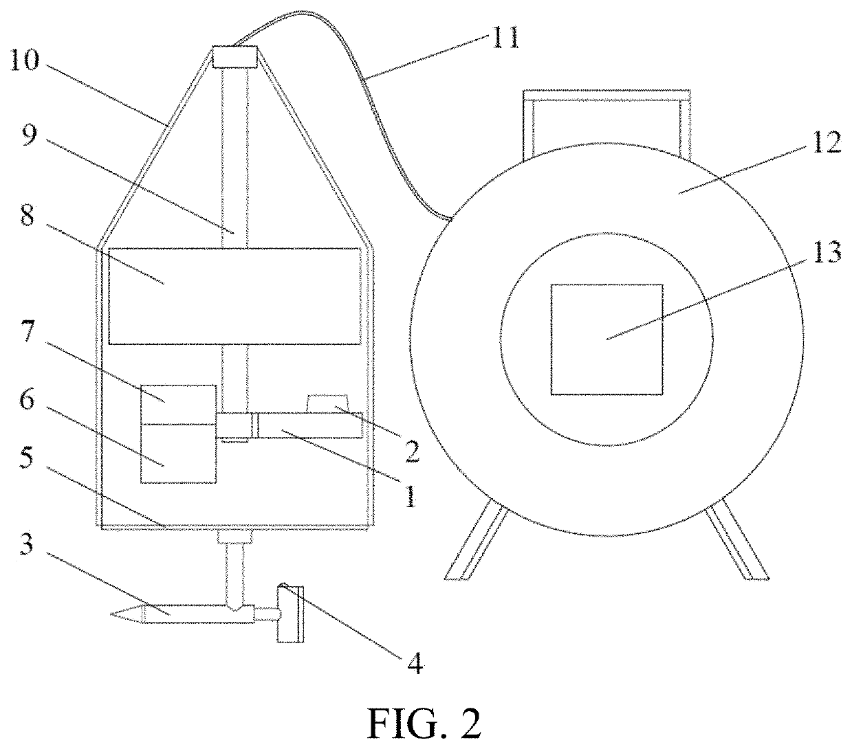
[0060]As shown in FIG. 2, an instrument for measuring velocity and direction of a groundwater flow of this embodiment includes:
[0061]an underwater detector as is shown in FIG. 1; and
[0062]a ground operation part, where the ground operation part and the underwater detector are connected through a cable 11.
[0063]In a specific implementation, the ground operation part includes a winch 12, an operation panel is disposed on the winch 13, and the operation panel 13 is connected to the processor module 7.
[0064]Specifically, the operation panel includes: a display, a relevant key, and a memory.
[0065]Where, the memory may be a data storage device such as a ROM or a USB.
embodiment iii
[0066]A working method of an instrument for measuring velocity and direction of a groundwater flow of this embodiment includes the following steps.
[0067]Step 1: Descend an underwater detector to a specified depth.
[0068]Before Step 1, the method also includes connecting a detector part and a winch through a cable, checking whether a device inside the detector is operating normally through a trial operation of an operation panel, checking watertightness of the detector, and turning on a light source on the velocity and direction indicator when there is no problem.
[0069]Specifically, using a borehole as an example, the detector part is placed into the borehole, and by observing the scale on the cable, the detector is descended to the specified depth at a constant speed by using a handle on the winch.
[0070]Step 2: Use the operation panel to start the underwater detector and set a rotation speed of the infrared sensor module after the instrument for measuring velocity and direction of a ...
PUM
 Abstract
Description
Claims
Application Information
 - R&D
- Intellectual Property
- Life Sciences
- Materials
- Tech Scout
- Unparalleled Data Quality
- Higher Quality Content
- 60% Fewer Hallucinations
Browse by: Latest US Patents, China's latest patents, Technical Efficacy Thesaurus, Application Domain, Technology Topic, Popular Technical Reports.
© 2025 PatSnap. All rights reserved.Legal|Privacy policy|Modern Slavery Act Transparency Statement|Sitemap|About US| Contact US: help@patsnap.com