
Electric motor

a technology of electric motors and motors, applied in the field of electric motors, can solve the problems of cooling performance of electric motors, affecting the cooling efficiency of electric motors, so as to improve the heat dissipation performance of oil, improve the cooling efficiency, and reduce the pressure loss of oil

Pending Publication Date: 2021-08-19
LG ELECTRONICS INC
View PDF0 Cites 1 Cited by
  • Summary
  • Abstract
  • Description
  • Claims
  • Application Information

AI Technical Summary

Benefits of technology

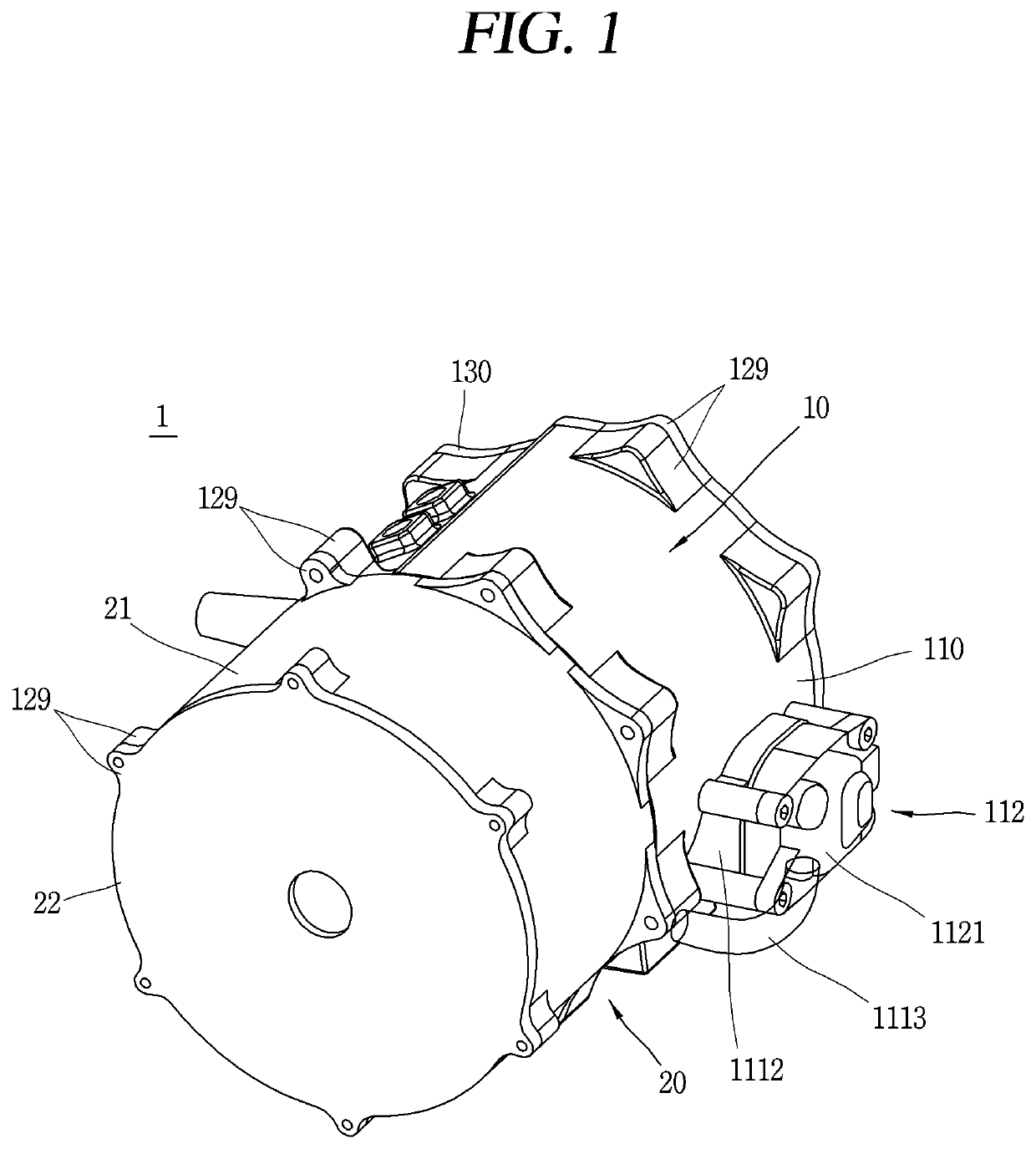
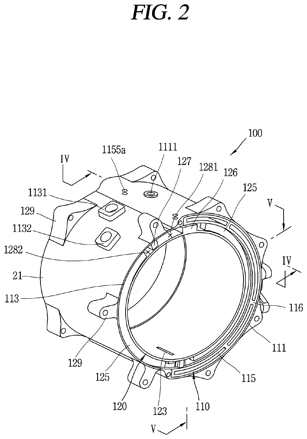
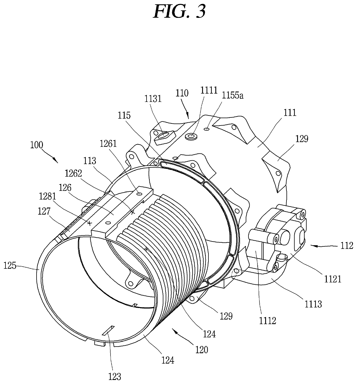
The present patent aims to solve issues in electric motors by providing a motor with a complex cooling passage structure that can be used for both oil cooling and water cooling. This improves cooling efficiency and performance, reduces costs, and makes the motor smaller. Additionally, the motor has an injection hole through which oil can be directly injected to the stator, and multiple oil pumps pumping oil in opposite directions on both sides of the motor housing, reducing resistance.

Problems solved by technology

However, Patent Document 1 does not have an injection device that directly injects oil into the stator coil, which generates the most heat, so there is a limit to improving the cooling performance of the motor, for example, there is a limit to cooling a drive motor for a vehicle of 50 kW or higher.
First, in case of the oil cooling type, cooling efficiency and cooling performance are good, but a heat exchanger must be separately provided at an outside of the housing to lower the temperature of oil, thereby causing an increase in cost and a disadvantage in downsizing the electric motor.
Second, in case of the water cooling type, there is an advantage in that a heat exchanger does not need to be separately provided, but there is a disadvantage in that cooling efficiency and cooling performance are deteriorated.
First, there is a problem in that the flow resistance increases when a length of the oil passage increases to dissipate more heat from the stator coil.
Second, there is a problem in that an oil pump must be increased to a large capacity when the passage resistance is large.
Third, when a large-capacity oil pump is attached to the motor housing, there is a problem that it becomes an obstacle to downsizing and lightening the motor.
Fourth, the stator core has a cylindrical shape in which a plurality of electrical steel sheets are stacked and coupled, and there is a problem in that it is difficult to fix the oil cooling passage in the slot of the motor.
Fifth, the oil pump is provided outside the motor housing, and the oil cooling passage is disposed to surround the stator coil on one side surface of the stator core at an inner side of the housing, and there is a problem in that it is difficult to form a connection structure for connecting the oil pump and the oil cooling passage.
Twenty-fourth, only coolant may be circulated in a low heating condition in which the external environment is at a low temperature to increase the viscosity of oil at a low temperature, thereby reducing the reliability of oil cooling.

Method used


Image

  • Electric motor
  • Electric motor
  • Electric motor

Examples


second embodiment

[0229]FIG. 8 is a cross-sectional view of a motor housing 200 showing a structure of a dual cooling passage according to the present disclosure.

[0230]The motor housing 200 according to a second embodiment may include an outer housing 210 and an inner housing 220. The dual cooling passages may include a plurality of first cooling passages 214 disposed inside the outer housing 210 and a second cooling passage disposed inside the inner housing 220.

[0231]Each of the plurality of first cooling passages 214 may extend in a circumferential direction inside the outer housing 210, and the plurality of first cooling passages 214 may be spaced apart along a length direction of the outer housing 210 by the plurality of passage formation portions 2151.

[0232]The second cooling passage may include a plurality of heat exchange cells 225 extending in a length direction inside the inner housing 220 and a plurality of communication passages connecting the plurality of heat exchange cells 225.

[0233]The...

third embodiment

[0238]FIG. 9 is a cross-sectional view of a motor housing 300 showing a structure of a dual cooling passage according to the present disclosure.

[0239]The motor housing 300 according to a third embodiment may include an outer housing 310 and an inner housing 320.

[0240]The dual cooling passages may include a plurality of first cooling passages 314 disposed inside the outer housing 310 and a second cooling passage 324 disposed inside the inner housing 320.

[0241]Each of the plurality of first cooling passages 314 may extend in a circumferential direction inside the outer housing 310, and the plurality of first cooling passages 314 may be spaced apart along a length direction of the outer housing 310 by the plurality of passage formation portions 3151.

[0242]The plurality of second cooling passages 324 may also be configured in the same manner as the plurality of first cooling passages 314.

[0243]The plurality of first and second cooling passages 324 are disposed to be open toward the insi...

fifth embodiment

[0335]FIG. 18 is a front view showing a dual passage structure of the motor housing 50 according to the present disclosure.

[0336]In the present embodiment, the motor housing 50 may be include triple walls 51, 52, 53.

[0337]The first wall 51 may define an outer circumferential surface of the motor housing 50, and the second wall 52 may be spaced apart from an inner side of the first wall 51 in a radial direction, and the third wall 53 may be spaced apart from an inner side of the second wall 52 in a radial direction.

[0338]A first cooling passage 54 may be disposed between the first and second walls 51, 52, and a second cooling passage 55 is disposed between the second and third walls 52, 53.


PUM


Abstract

The present invention relates an electric motor comprising: a motor housing; a stator disposed inside the motor housing; and a rotor rotatably installed inside the stator, wherein the motor housing comprises: an outer housing including a first cooling fluid channel through which oil flows; an inner housing disposed inside the outer housing; and a plurality of injection holes formed in the inner housing to communicate with the first cooling fluid channel, so as to inject the oil to the inside of the inner housing, and the inner housing comprises: a plurality of fluid channel forming parts extending inside the inner housing along the circumferential direction thereof; a fluid channel guide extending along the lengthwise direction of the inner housing; and a common header disposed between the plurality of fluid channel forming parts and the fluid channel guide to distribute the cooling water to the second cooling fluid channel or to collect the cooling water from the second cooling fluid channel.

Description

BACKGROUND1. Technical Field[0001]The present disclosure relates to an electric motor having an oil cooling and water cooling complex cooling passage structure.2. Description of the Related Art[0002]In recent years, electric vehicles (including hybrid vehicles) having an electric motor as a driving source for the vehicle have excellent fuel economy and have been launched as future vehicles.[0003]In general, an electric motor includes a rotor and a stator, and the rotor may be rotatably provided inside the stator.[0004]The stator has a stator coil wound around a stator core, and when current flows through the stator coil to rotate the rotor, heat is generated from the stator coil, and technologies for cooling the heat generated from the electric motor have been developed.[0005]In a drive system including a motor of an electric vehicle and an inverter for driving the motor, cooling heat generated by the motor and the inverter perform an important role in the aspects of downsizing and ...

Claims


Application Information

Patent Timeline
IPC IPC(8): H02K5/20B60K11/02H02K9/19
CPCH02K5/203H02K9/19B60K11/02B60K1/00B60K2001/006
Inventor KIM, JONGSUKWAK, TAEHEEMOON, JUNGWOOKJO, CHANGHUM
Owner LG ELECTRONICS INC
Learn More