Mounting structure for power storage device

Pending Publication Date: 2021-07-22
TOYOTA JIDOSHA KK
View PDF20 Cites 0 Cited by
  • Summary
  • Abstract
  • Description
  • Claims
  • Application Information

AI Technical Summary

Benefits of technology

The patent aims to provide a mounting structure for a power storage device that can protect the device from damage caused by impacts during a collision. The current mounting structure may be expensive due to the need for costly reinforced parts. The technical effect of the patent is to provide a more affordable solution to suppress impact transmission to the power storage stack in the housing case during a collision.

Problems solved by technology

Thus, the cost for the mounting structure for a power storage device tends to be relatively high.

Method used


Image

  • Mounting structure for power storage device
  • Mounting structure for power storage device

Examples


case 52

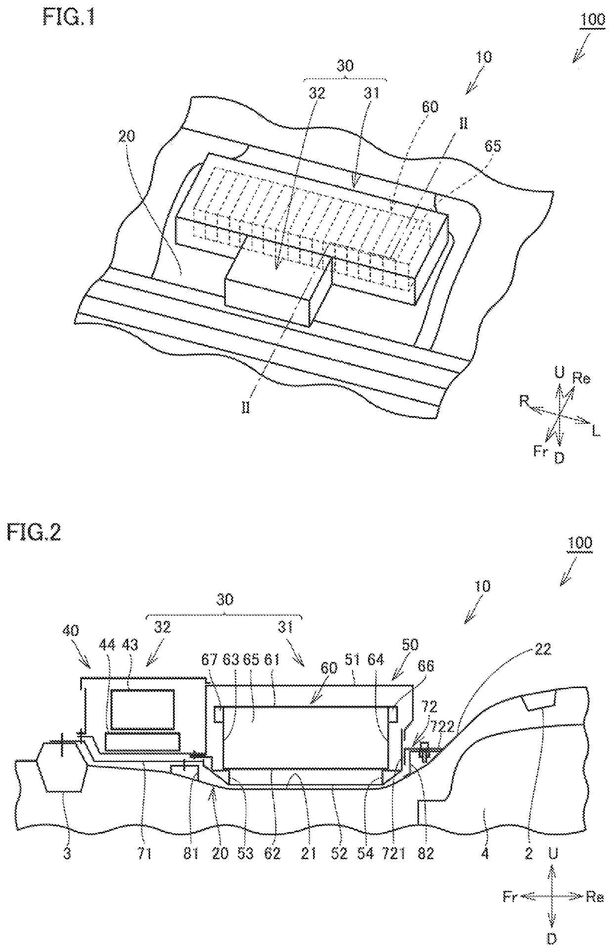
[0044]Inside lower case 52, a first mounting portion 53 and a second mounting portion 54 are provided, on which power storage stack 60 is to be mounted. First mounting portion 53 and second mounting portion 54 are disposed inside lower case 52 to provide a gap between first mounting portion 53 and second mounting portion 54 in the front-rear direction of the vehicle. Lower surface 62 of power storage stack 60 has both ends in the front-rear direction of the vehicle. Each of both ends is fixed to a corresponding one of first mounting portion 53 and second mounting portion 54. Power storage stack 60 is disposed to provide a gap between power storage stack 60 and a rear wall 52b (see FIG. 3) of lower case 52.

[0045]Upper case 51 has a substantially box shape that opens downward. Uppercase 51 is provided to cover the upper surface 61 side of power storage stack 60. Upper case 51 is fixed to lower case 52.

[0046]Second unit 32 mainly includes a second case portion 40, a junction box 43, an...

case 51

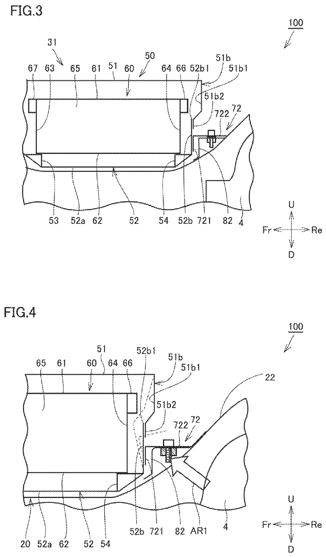
[0055]Upper case 51 provided so as to cover the upper side of power storage stack 60 has a wall 51b that faces, from the rear side, the upper portion of rear surface 64 of power storage stack 60. Wall 51b has a lower end portion 51b2 at a position lower than the terminal portion (the above-mentioned first terminal portion 66) provided on rear surface 64 of power storage stack 60. Lower end portion 51b2 is fixed to rear wall 52b of lower case 52, for example.

[0056]On the rear side of the above-mentioned terminal portion (the above-mentioned first terminal portion 66), wall 15b has a bulging portion 51b1 that bulges more rearward than lower end portion 51b2. In other words, in the front-rear direction of the vehicle, the distance from rear surface 64 of power storage stack 60 to bulging portion 51b1 is longer than the distance from rear surface 64 to lower end portion 51b2.

[0057]Furthermore, rear wall 52b of lower case 52 has an upper end 52b1 located at a position lower than upper su...


PUM


Abstract

A mounting structure for a power storage device includes: a power storage device including a power storage stack and a housing case; a floor member; and a rear bracket. The housing case includes a lower case having a rear wall, and an upper case. The floor member is provided with an attachment portion for attaching the rear bracket. The rear bracket includes a front end portion and a rear end portion that is attached to the attachment portion. The power storage stack is disposed inside the housing case to provide a gap between the power storage stack and the rear wall. The front end portion of the rear bracket is fixed to the rear wall to be located between an upper surface and a lower surface of the power storage stack in an up-down direction.

Description

[0001]This nonprovisional application is based on Japanese Patent Application No. 2020-006576 filed on Jan. 20, 2020 with the Japan Patent Office, the entire contents of which are hereby incorporated by reference.BACKGROUNDField[0002]The present disclosure relates to a mounting structure for a power storage device in a vehicle.Description of the Background Art[0003]Vehicles such as an electric vehicle and a hybrid vehicle are equipped with a power storage device for supplying electric power to a motor. The power storage device includes a housing case in which a power storage stack is housed. The power storage device is fixed to a floor panel, for example.[0004]As a conventional mounting structure for a power storage device, Japanese Patent No. 5733089 discloses a technique by which a bracket is used to fix the front side of a housing case to a cross member of a vehicle and a reinforce (a reinforcement member) is used to fix the rear side of the housing case to a base mount portion p...

Claims


Application Information

Patent Timeline
IPC IPC(8): B60K1/04
CPCB60K1/04B60K2001/0438B60L50/64B62D25/20B60K2001/0405B60K2001/0416B60K2001/0433Y02T10/70Y02E60/10H01M50/249H01M50/262H01M2220/20B60Y2200/91B60Y2200/92Y02T10/62Y04S10/126
Inventor SHIMADA, MASAKI
Owner TOYOTA JIDOSHA KK
Why Eureka
Try Eureka