Buckle

a buckle and side release technology, applied in the field of buckles, can solve the problems of increasing the risk of damage to both parts, difficult inserting of parts, and not preventing the movement of the locking legs outward

Active Publication Date: 2021-07-22
DURAFLEX HONG KONG
View PDF13 Cites 1 Cited by
  • Summary
  • Abstract
  • Description
  • Claims
  • Application Information

AI Technical Summary

Benefits of technology

[0009]The buckle according to the invention forms a male buckle portion of a two-piece buckle assembly in conjunction with a female buckle portion. The female buckle portion has a top face, a bottom face, and an interior cavity for receiving the male buckle portion. The bottom face of the female buckle portion has a cutout forming locking edges along sides of the bottom face. Each of the locking legs of the male buckle portion has a locking protrusion located on at least a bottom face of the locking legs. The male buckle portion is locked to the female buckle portion by inserting the male buckle portion into the cavity until the locking protrusions engage the locking edges of the female buckle portion. The female buckle portion has a plurality of guide elements, so that during insertion of the male portion into the female portion, the central leg is guided between the guide elements to keep the male portion in alignment with the female portion. The guide elements separate the interior of the female portion into three channels. The central channel accommodates the central leg, and the outer channels accommodate the two locking legs. The longer central leg helps position the male portion in proper alignment with the female portion prior to the locking legs entering the female portion.
[0010]The female portion is constructed to have open sides, so that when the male portion is connected to the female portion, an entire length of each locking leg is exposed outside the female portion. This makes it easier for the user to press the locking legs together to release the locking legs, as a larger portion of each locking leg is available for contact with the user's fingers, and there is no risk of interference by the structure of the female portion during release.

Problems solved by technology

The drawback of this structure is that it does not prevent the locking legs from moving outward along the full extent of the hinge point.
This can make the male part difficult to insert into the female part, as well as increase the risk of damage to both parts.

Method used


Image

  • Buckle
  • Buckle
  • Buckle

Examples


Embodiment Construction

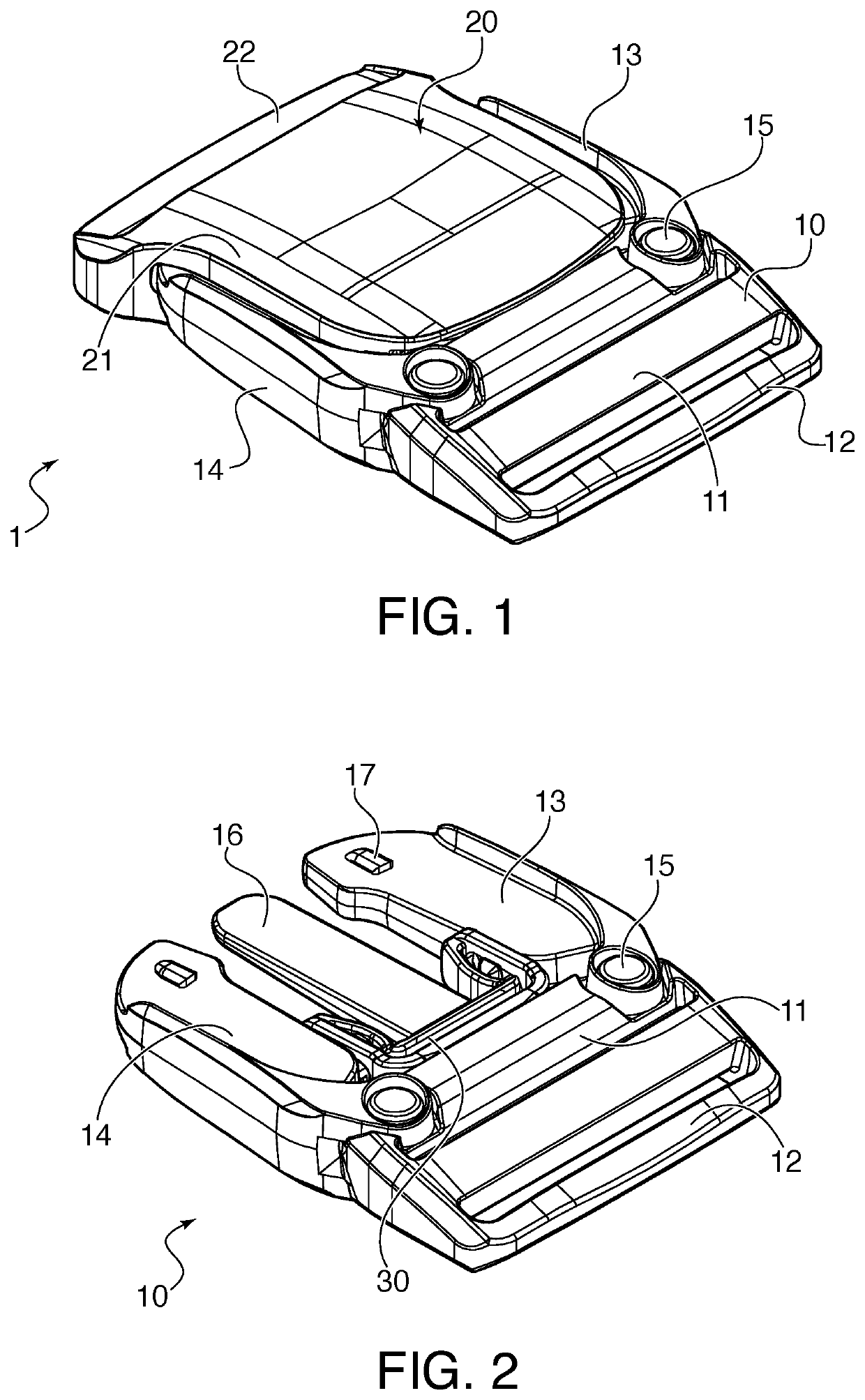
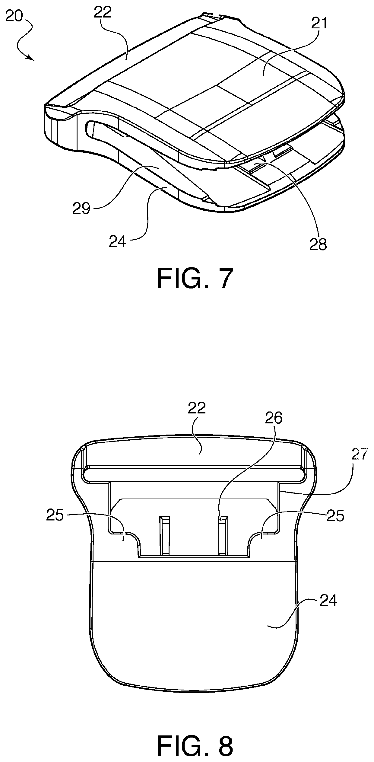
[0022]Referring now in detail to the drawings FIG. 1 shows a perspective view of the buckle assembly 1 according to the invention. Buckle assembly 1 is formed of a male buckle portion 10 and a female buckle portion 20. As also shown in FIGS. 2 and 3, male buckle portion 10 has a main body 11, a strap connecting bar 12 connected to main body 11, and two locking legs 13, 14. Locking legs 13, 14 are formed separately from main body 11 and are pivotably connected to main body 11 via hinge pins 15. A central leg 16 is fixedly connected to main body 11 and extends between locking legs 13, 14. Central leg 16 is longer then locking legs 13, 14. Locking legs 13, 14, have locking protrusions 17 located thereon for locking engagement with female buckle portion 20, as explained below.

[0023]A spring 30 is attached to locking legs 13, 14. As shown in FIGS. 4 and 5, spring 30 is formed of a closed loop that is bent into a U-shape, to form outer walls 32, rear wall 31 and inner wall 37. Engagement ...


PUM


Abstract

A buckle has a main body, a strap retaining bar connected to the main body, two locking legs formed as separate pieces from the main body and pivotably connected to the main body; and a spring disposed between the two locking legs. The spring is attached to both of the locking legs, and exerts a force against the locking legs when they are pressed inward toward each other. The spring keeps the locking legs in an outwardly tensioned position, but does not let the legs flex outwardly in an unlimited manner, since the spring is directly connected to the legs. The spring allows the main body and locking legs to be formed of an inflexible material, such as metal. The locking legs are separate pieces from the main body and are connected to the main body via a pivot pin or other hinged mechanism.

Description

BACKGROUND OF THE INVENTION1. Field of the Invention[0001]The present invention relates to a two-piece side-release buckle. In particular, the invention relates to a side release buckle in which the locking legs are tensioned in place by a separate spring.2. The Prior Art[0002]Conventional side release buckles are formed by a male part having two locking legs that engage a female part through slots in the side walls of the female part. The locking legs extend through the slots and are locked in place by locking flanges that abut the sides of the slots. The male part is released from the female part by the user squeezing the locking legs together until the locking flanges clear the slots and the male part can exit from the female part. In this type of structure, which is shown for example in U.S. Pat. No. 7,020,939B2, the locking legs are formed as one piece with the rest of the male part, and the spring force of the plastic keeps the legs in the locked position until the user releas...

Claims


Application Information

Patent Timeline
Patent Type & Authority Applications(United States)
IPC IPC(8): A44B11/16
CPCA44B11/16A44B11/2592A44B11/266
Inventor CHAN, YICK FAI
Owner DURAFLEX HONG KONG
Why Eureka
Try Eureka