
Surgical positioner apparatus, system, and method for securing to a side rail of support table

a technology of support table and side rail, which is applied in the field of surgical positioners, can solve the problems of difficult sterilization of components, and high cost of support table, and achieve the effects of avoiding hyperextension of knee and patient's leg, reducing burdens and unneeded forces on joints, and simple cleanable construction

Inactive Publication Date: 2021-07-08
INNOVATIVE MEDICAL PRODS
View PDF15 Cites 1 Cited by
  • Summary
  • Abstract
  • Description
  • Claims
  • Application Information

AI Technical Summary

Benefits of technology

The hip positioning system helps give better access to the patient during surgery.

Problems solved by technology

The anterior approach or direct anterior approach (DAA) provides the least disruptive surgical approach but is more technically demanding from a surgeon's perspective because of the need for increased awareness of the local anatomy, reduced visibility, and the use of smaller incisions.
These support tables are expensive, and the components heavy and difficult to sterilize.
In addition, hip positioning systems utilize a perineal post that to can cause injury to muscles and tendons as well as contribute to postoperative pain and increased convalescence in a total hip replacement surgery.
A mobile support in conjunction with the support table requires additional space, expensive, and support set up time in connection with a total hip replacement surgical procedure.
Conventional surgical positioners for the direct anterior approach are more technically demanding from a surgeon's perspective because the opposite leg is held and manipulated with increased demands for larger limbs and weight.
Conventional hip systems have attachment arms that are heavy and provide challenges for surgeons when operating on larger limbs due to the weight.

Method used


Image

  • Surgical positioner apparatus, system, and method for securing to a side rail of support table
  • Surgical positioner apparatus, system, and method for securing to a side rail of support table
  • Surgical positioner apparatus, system, and method for securing to a side rail of support table

Examples


Embodiment Construction

[0066]Non-limiting embodiments of the present invention will be described below with reference to the accompanying drawings, wherein like reference numerals represent like elements throughout. While the invention has been described in detail with respect to the preferred embodiments thereof, it will be appreciated that upon reading and understanding of the foregoing, certain variations to the preferred embodiments will become apparent, which variations are nonetheless within the spirit and scope of the invention.

[0067]The terms “a” or “an”, as used herein, are defined as one or as more than one. The term “plurality”, as used herein, is defined as two or as more than two. The term “another”, as used herein, is defined as at least a second or more. The terms “including” and / or “having”, as used herein, are defined as comprising (i.e., open language). The term “coupled”, as used herein, is defined as connected, although not necessarily directly, and not necessarily mechanically.

[0068]R...


PUM


Abstract

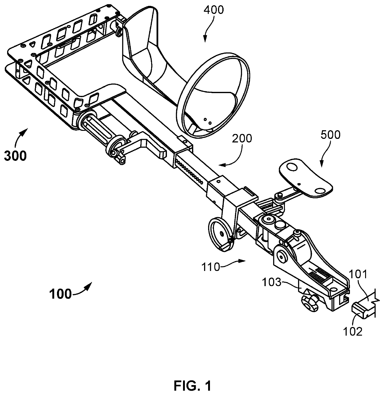
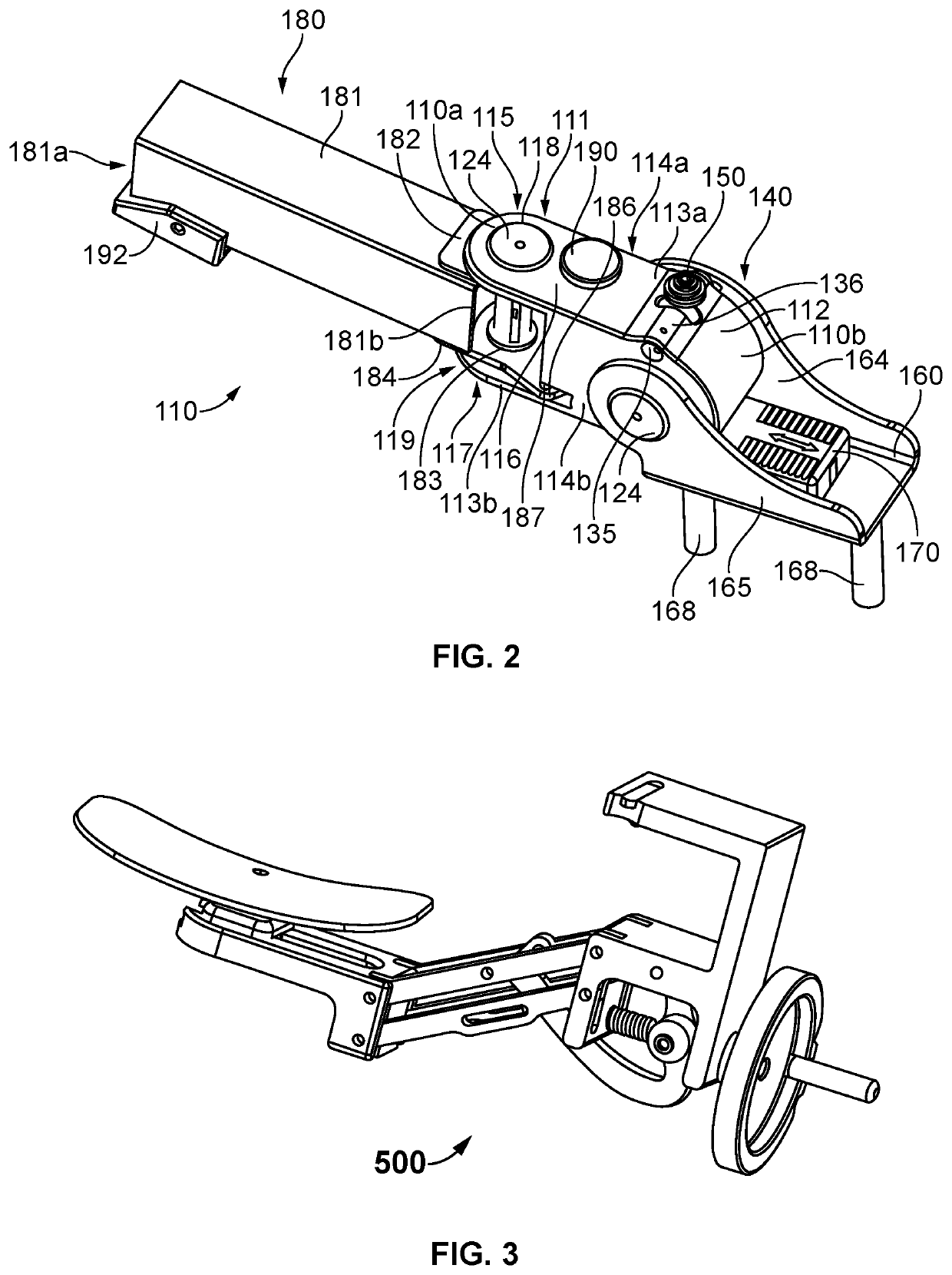
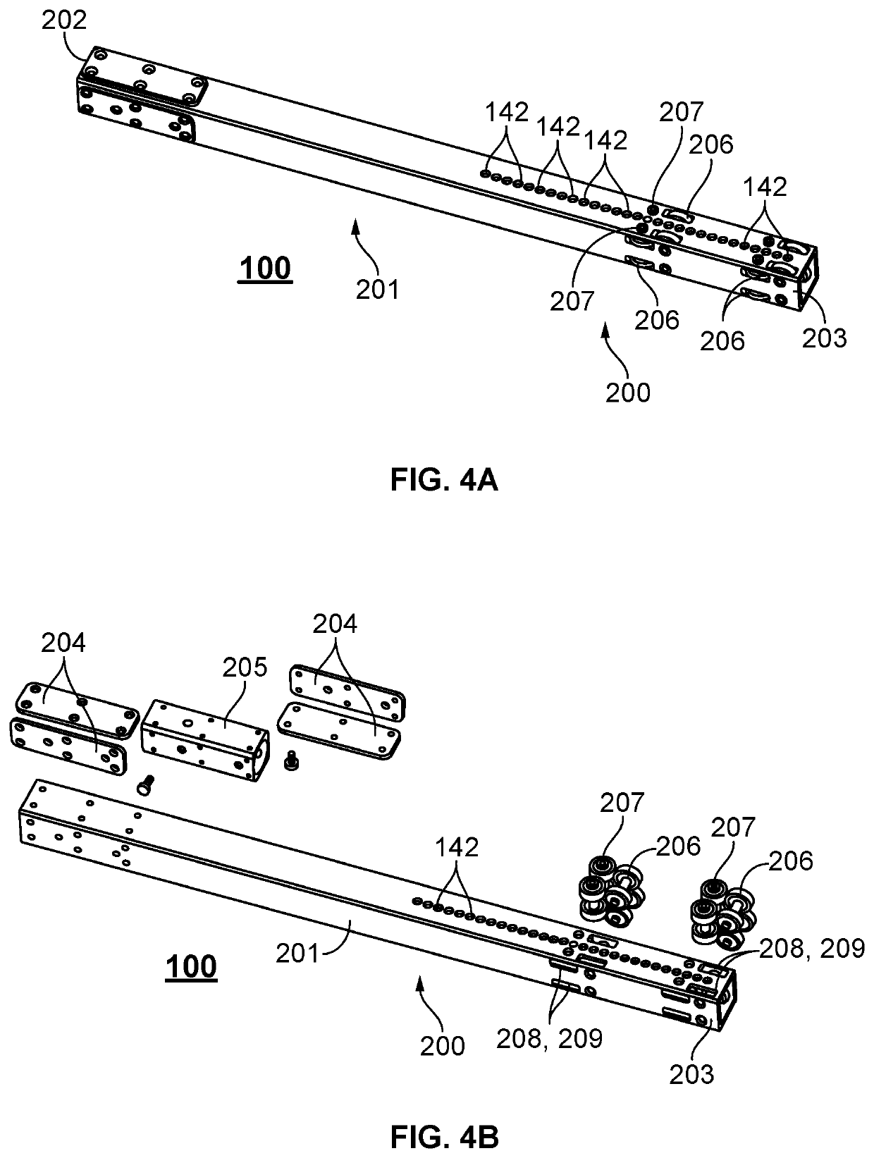
A surgical positioner system for a support table having a side rail having a clamp assembly for attaching to the side rail. The clamp assembly having a spring and a locking assembly with movement in the x- and y-plane; and extension provides sliding movement in the z-plane. The extension being dimensioned to be operably connected to said clamp assembly and a rotational assembly. A rotational assembly has a portion for operably connecting to the extension, a device attachment portion, and a rotational assembly operably connected to the device attachment portion for providing rotational thereof. A boot having a holder portion and a flexible attachment can be attached to the device attachment portion. The surgical positioner provides motion from different force factors causing multiple components to move in a coordinated way using such established pivots and useful in performing various surgical procedures including direct anterior approach total hip replacement surgery.

Description

CROSS REFERENCE TO RELATED APPLICATIONS[0001]This application claims the benefit of U.S. Provisional Application No. 62 / 916,796, filed Oct. 17, 2019, which is incorporated entirely.FIELD OF THE INVENTION[0002]The present invention relates to surgical positioners for hip replacement procedures and, more particularly, to an improved surgical positioner connectable to the side rail of a surgical support table facilitating bilateral surgeries and is useful for direct anterior approach total hip replacement surgery and other orthopedic surgical procedures.BACKGROUND OF THE INVENTION[0003]Conventional hip replacement surgeries position the patient to access the surgical site. The anterior approach or direct anterior approach (DAA) provides the least disruptive surgical approach but is more technically demanding from a surgeon's perspective because of the need for increased awareness of the local anatomy, reduced visibility, and the use of smaller incisions. In this approach, the incision ...

Claims


Application Information

Patent Timeline
Patent Type & Authority Applications(United States)
IPC IPC(8): A61G13/00A61G13/10A61G13/12
CPCA61G13/0081A61G13/101A61G13/129A61G13/1245A61G13/125
Inventor KOVACS, TAMAS
Owner INNOVATIVE MEDICAL PRODS
Learn More