Al technical title is built by PatSnap Al team. It summarizes the technical point description of the patent document.
a technology of fit pods and pods, applied in the direction of helmets, protective garments, synthetic resin layered products, etc., can solve the problems of structure deformation or eventually breakage, and achieve the effects of improving core ventilation ability, great stiffness and strength-to-weight ratio, and excellent energy absorption
Pending Publication Date: 2021-06-24
SPARK MEDICAL INC
View PDF2 Cites 10 Cited by
Summary
Abstract
Description
Claims
Application Information
AI Technical Summary
This helps you quickly interpret patents by identifying the three key elements:
Problems solved by technology
Method used
Benefits of technology
[0005]There exists a need to create an improved microlattice layer that provides a greater stiffness, and strength-to-weight ratio, comfort as well as providing excellent energy absorption for use in different applications. Furthermore, microlattice offers additional advantages compared to conventional lattices, resulting in improved capability of core ventilation and heat exchange, which eliminates the problem of moisture absorption and potential material properties degradation. The microlattice layer and / or structure comprises an interconnected network of a plurality of filaments (e.g., or struts) that can be tailored to specific applications by modifying the filament dimensions, filament materials, units cell shape and geometry, interior angles, filament configuration and / or any combination thereof.
Problems solved by technology
However, the greater the strain that exceeds the elastic limit of the structure, the structure may permanently deform or eventually break.
Method used
Image
Click on the blue label to locate the original text in one second.
Reading with bidirectional positioning of images and text.
Examples
example embodiments
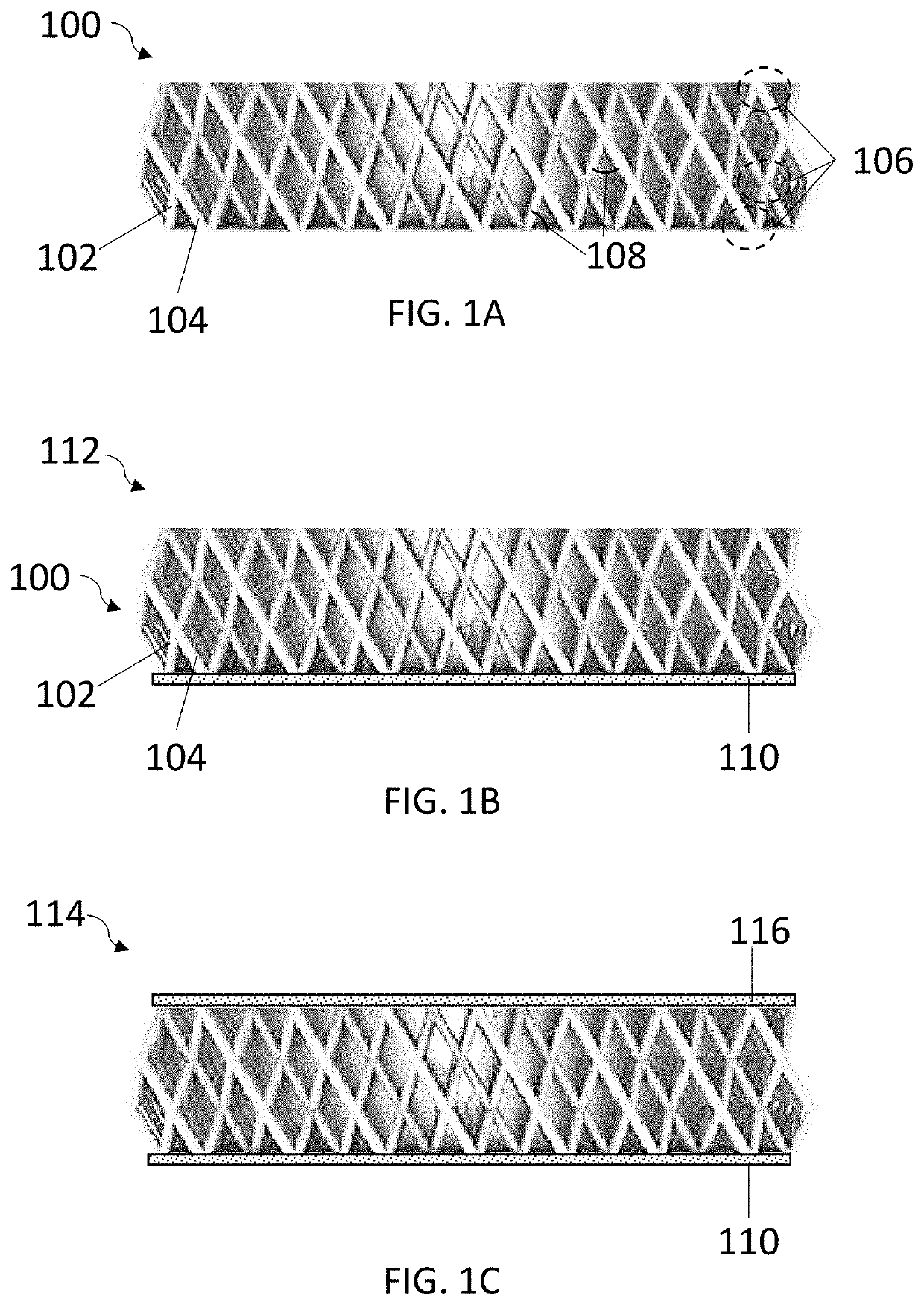
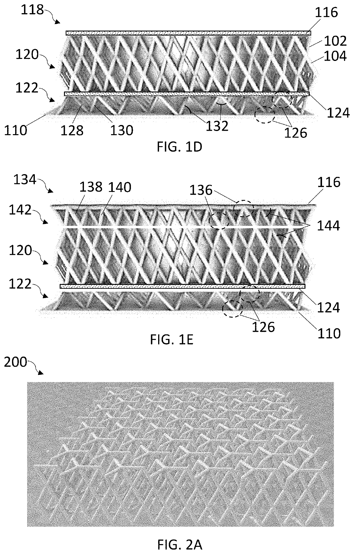
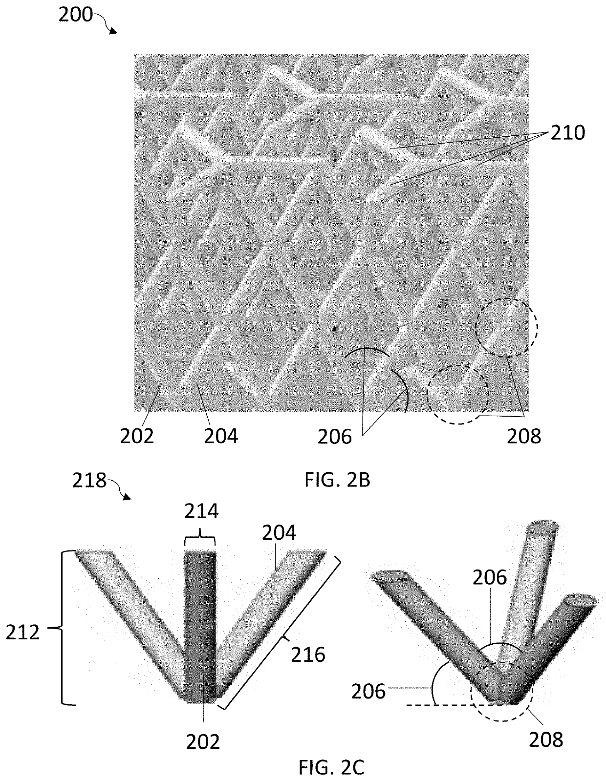
[0159]Claim 1. The micro-lattice layer or structure comprising: a first plurality of filaments and a second plurality of filaments, the first plurality of filaments having a first end and a second end, the second plurality of filaments intersects with the first plurality of filaments creating at least two intersection points or nodes at the first end and second end, the first plurality of filaments and the second plurality of filaments having a longitudinal axis, the second plurality of filaments extending non-perpendicularly in different directions from the first plurality of filaments; and a plurality of interior angles, the plurality of interior angles disposed adjacent to the at least two nodes;
[0160]The micro-lattice layer of claim 1, wherein the first plurality of filaments further comprises a mid-end, the mid end disposed anywhere along the longitudinal axis between the first and second end.
[0161]Claim 2. The micro-lattice layer or structure comprising: a first plurality of f...
PUM
Property
Measurement
Unit
surface area
aaaaa
aaaaa
Young's modulus
aaaaa
aaaaa
interior angles
aaaaa
aaaaa
Abstract
A microlattice structure may be used for a variety of different applications with a protective helmet assembly. The three-dimensional microlattice layer comprising a plurality of interconnected filaments extending along at least three different directions from a plurality of nodes. The microlattice layer may further comprise at least one material layer extending laterally between and interconnecting at least two or more nodes. The at least one material layer may be configured to transversely and rotationally constrain the nodes to increase the overall compressive strength and stiffness of the microlattice structure. The at least one material layer may comprise a single, continuous layer and/or a plurality of material layer segments. The microlattice layer may comprise a single, continuous layer or a plurality of microlattice layer segments. The microlattice layer may be stacked, the stacked microlattice layers may further comprise one or more material layers and/or one or more impact mitigation layers.
Description
CROSS-REFERENCE TO RELATED APPLICATIONS[0001]This is a continuation-in-part application of Patent Cooperation Treaty Application Serial No. PCT / US2019 / 061157, entitled “MicroLattice Layers,” filed on Nov. 13, 2019, which claims benefit of U.S. Provisional Patent Application No. 62 / 760,319, entitled “AirCrew Helmet System,” filed Nov. 13, 2018, and U.S. Provisional Application No. 62 / 898,443, entitled “Microlattice Layers,” filed Sep. 10, 2019, the disclosures of which are incorporated by reference herein in their entireties.[0002]This application further claims the benefit of U.S. Provisional Patent Application No. 62 / 960,827 entitled “Custom Manufactured Fit Pods,” filed Jan. 14, 2020, the disclosure of which is incorporated by reference herein in its entirety.TECHNICAL FIELD[0003]The present invention relates to methods, devices, and systems for conformal body protection. More specifically, the invention relates to methods, devices, and systems for tailored micro-lattice layers an...
Claims
Application Information
Patent Timeline
Application Date:The date an application was filed.
Publication Date:The date a patent or application was officially published.
First Publication Date:The earliest publication date of a patent with the same application number.
Issue Date:Publication date of the patent grant document.
PCT Entry Date:The Entry date of PCT National Phase.
Estimated Expiry Date:The statutory expiry date of a patent right according to the Patent Law, and it is the longest term of protection that the patent right can achieve without the termination of the patent right due to other reasons(Term extension factor has been taken into account ).
Invalid Date:Actual expiry date is based on effective date or publication date of legal transaction data of invalid patent.
Patent Type & Authority Applications(United States)