Switch module
a switch module and module technology, applied in the field of switch modules, can solve the problems of increasing the insertion loss of this series-connected switch, difficult to find suitable values, and difficult to reduce the insertion loss of the switch module including the shunt-connected switch, so as to reduce the insertion loss of the switch module
- Summary
- Abstract
- Description
- Claims
- Application Information
AI Technical Summary
Benefits of technology
Problems solved by technology
Method used
Image

Examples
first embodiment
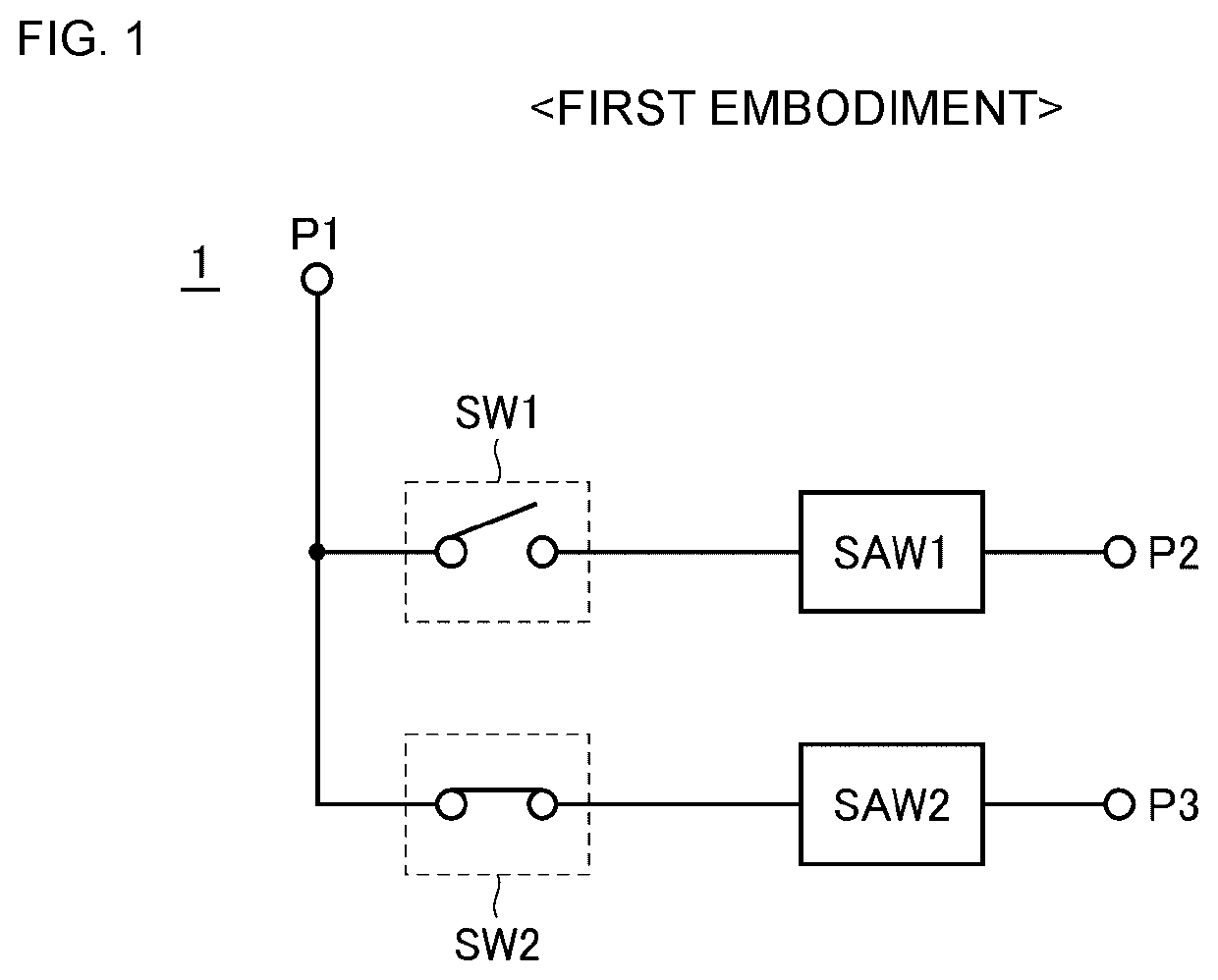
[0041]FIG. 1 is a circuit diagram of a switch module 1 according to a first embodiment. As shown in FIG. 1, the switch module 1 includes a common terminal P1, input / output terminals P2 and P3, first and second filters SAW1 and SAW2, which are surface acoustic wave (SAW) filters, and first and second switches SW1 and SW2. The pass band of the second filter SAW2 is included in the stop band of the first filter SAW1. The switch module 1 is a single-pole double-throw (SPDT) switch module. Alternatively, the switch module 1 may be a SPnT (n is three or greater) switch module.
[0042]The common terminal P1 corresponds to a first terminal of an embodiment of the disclosure. The pass band of the first filter SAW1 corresponds to a first frequency band of an embodiment of the disclosure, and the stop band of the first filter SAW1 corresponds to a second frequency band of an embodiment of the disclosure. The pass band of the second filter SAW2 corresponds to a third frequency band of an embodime...
first modified example of first embodiment
[0075]In the first embodiment, the pass band of the first filter SAW1 does not overlap that of the second filter SAW2, and thus, the switch module 1 does not include shunt-connected switches. However, if the pass band of one filter overlaps that of another filter in a switch module, the provision of shunt-connected switches is necessary. In a first modified example of the first embodiment, the provision of shunt-connected switches is necessary because the pass band of one filter overlaps that of another filter. In the first modified example, the configurations of elements designated by like reference numerals of the first embodiment are similar to those of the first embodiment, and an explanation thereof will thus be omitted.
[0076]FIG. 8 is a circuit diagram of a switch module 1A according to the first modified example of the first embodiment. The switch module 1A includes an input / output terminal P4, a third switch SW3, a third filter SAW3, which is a SAW filter, and fourth and fif...
second modified example of first embodiment
[0085]In the first embodiment and the first modified example thereof, the switch modules 1 and 1A include the common terminal P1 and plural input / output terminals connected to individual SAW filters. The single common terminal P1 is used for all plural input / output terminals. In a second modified example of the first embodiment, a switch module includes two common terminals. The configuration between each SAW filter and the common terminal P1 in the second modified example is similar to that of the first modified example of the first embodiment, and an explanation thereof will thus be omitted.
[0086]FIG. 9 is a circuit diagram of a switch module 1B according to the second modified example of the first embodiment. As shown in FIG. 9, the switch module 1B includes a common terminal P2B (second terminal), seventh, eighth, and ninth switches SW7, SW8, and SW9, and tenth and eleventh switches SW10 and SW11. The tenth and eleventh switches SW10 and SW11 are shunt-connected switches.
[0087]T...
PUM
 Abstract
Description
Claims
Application Information
 - R&D
- Intellectual Property
- Life Sciences
- Materials
- Tech Scout
- Unparalleled Data Quality
- Higher Quality Content
- 60% Fewer Hallucinations
Browse by: Latest US Patents, China's latest patents, Technical Efficacy Thesaurus, Application Domain, Technology Topic, Popular Technical Reports.
© 2025 PatSnap. All rights reserved.Legal|Privacy policy|Modern Slavery Act Transparency Statement|Sitemap|About US| Contact US: help@patsnap.com