
Systems and methods for monitoring slope stability

a technology of slope stability and monitoring system, applied in the field of systems and methods for monitoring slope stability, can solve the problems of significant challenge in monitoring unconsolidated materials for mechanical stability and fluid accumulation, unconsolidated materials, occupational hazards, etc., and achieve the effect of minimal signal loss

Pending Publication Date: 2021-05-27
MUON VISION INC
View PDF0 Cites 6 Cited by
  • Summary
  • Abstract
  • Description
  • Claims
  • Application Information

AI Technical Summary

Benefits of technology

The patent describes methods for optimizing the economic value of crushed ore material based on factors such as process fluid distribution and the risk of slope collapse or liquefaction. Additionally, the patent aims to determine the location and distance from pre-existing tunnels during underground mining drilling operations to reduce the risk of intersecting them. These methods may ultimately improve the efficiency and safety of mining operations.

Problems solved by technology

The monitoring of unconsolidated materials for mechanical stability and fluid accumulation is a significant challenge.
Slope failures and landslides of unconsolidated materials, soft soils and sediments generally occur when the static stress due to the weight of the accumulation of material exceeds the shear strength of the material itself.
Such monitoring is critical in the mining industry, where personnel are frequently in close proximity to large quantities of unconsolidated materials which pose an occupational hazard.
A heap failure can severely damage valuable mining and material handling equipment and is hazardous to any person nearby.
For leaching pads, that are generally built above a lined surface, the most common stability failure mechanism is due to block or translational type failure along the interface with the lowest shear strength parameters which is typically the liner.
Another problem is that in certain mining operations, sludges and fluids from a variety of chemical refining or hydrometallurgical processes accumulate in large tailing ponds.
In most cases, slope failure occurs within an accumulation of unconsolidated material and depends strongly on the volume of fluids within the pore space of the material itself.
Excessive fluid accumulations lead to build up of pore pressure within the material, which in turn results in reduced frictional and cohesive strengths, for example, a loss of overall shear strength.
Under these conditions, the slope of unconsolidated material will ultimately fail under its own weight.
In the case of a mining heap, where fluid may be trapped in varying concentration due to complex fluid percolation patterns and flow barriers (such as permeability plugs), slope failure may also occur at the toe or at the top of the heap.
Sudden slope failure is also referred to as slope collapse or liquefaction and poses an ongoing risk for the mining, construction and cargo industries as well as whenever stockpiling of large quantities of materials occurs.
It is also a natural risk, which may result for instance in landslide and soil movement across a variety of terrains and environments.
These risks are often compounded by events such as heavy rains, snow melt and the occurrence of seismic events.
Slope failure may lead to tragic loss of life, environmental damage, damage to specialized equipment or infrastructure, and significant loss of productive time.
However, dewatering can be a complex and expensive process with a wide range of techniques and equipment available.
Improper deployment of dewatering strategies will not only result in excess costs, but it can also fail to prevent slope failure as intended.
Drilling or breaking through an abandoned mine tunnel filled with water can pose considerably risk of loss of equipment, asset value or even human lives.
Many underground mines can only operate with pumps actively removing water that seeps from the subsurface into tunnels and other structures.
The risk of changing fluid levels is present in rocky but highly porous materials such as limestones or karst.

Method used


Image

  • Systems and methods for monitoring slope stability
  • Systems and methods for monitoring slope stability
  • Systems and methods for monitoring slope stability

Examples


Embodiment Construction

[0083]This disclosure is not limited to the particular systems, devices and methods described, as these may vary. The terminology used in the description is for the purpose of describing the particular versions or embodiments only, and is not intended to limit the scope.

[0084]As used in this document, the singular forms “a,”“an,” and “the” include plural references unless the context clearly dictates otherwise. Unless defined otherwise, all technical and scientific terms used herein have the same meanings as commonly understood by one of ordinary skill in the art. Nothing in this disclosure is to be construed as an admission that the embodiments described in this disclosure are not entitled to antedate such disclosure by virtue of prior invention. As used in this document, the term “comprising” means “including, but not limited to.”

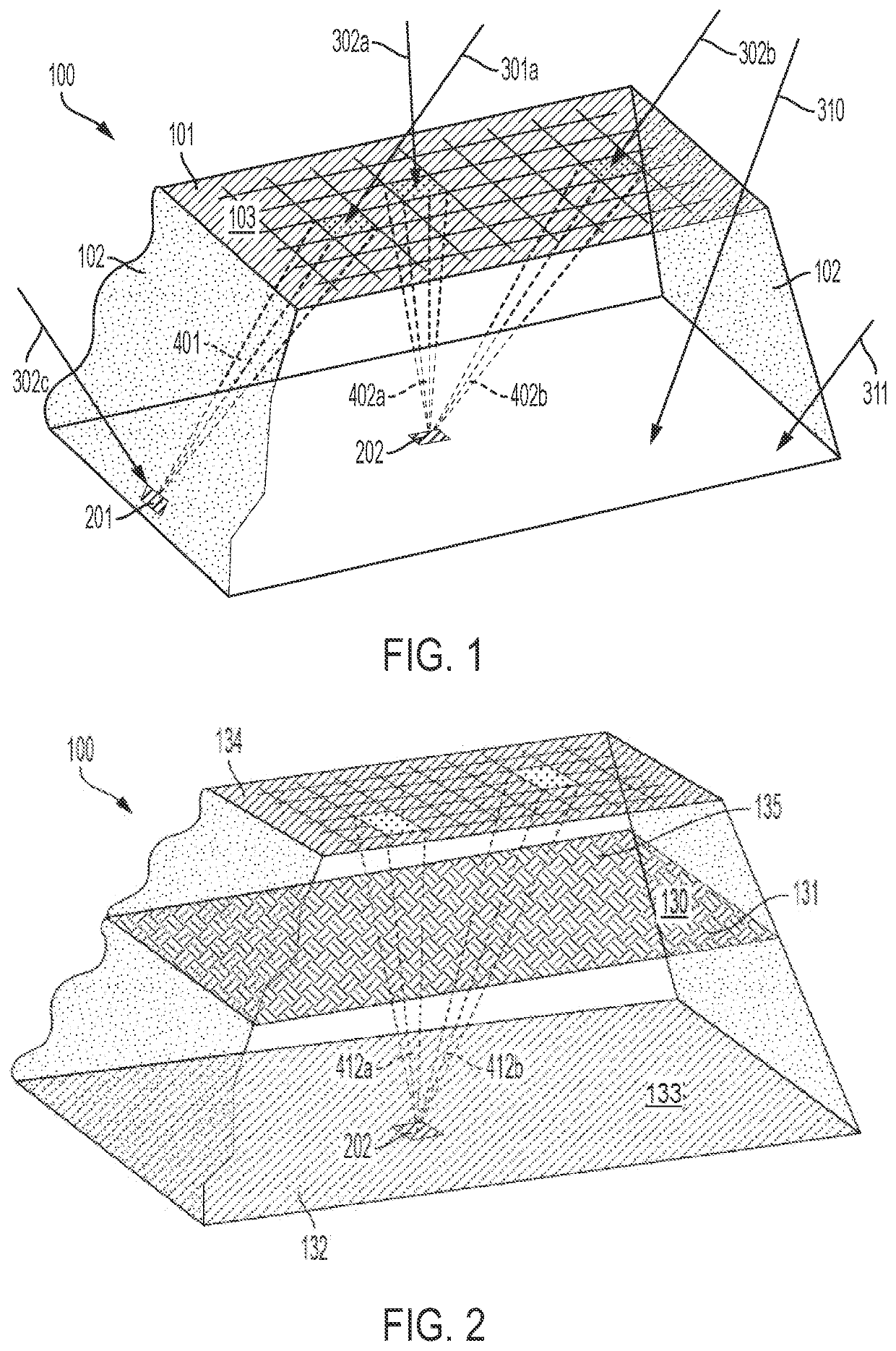
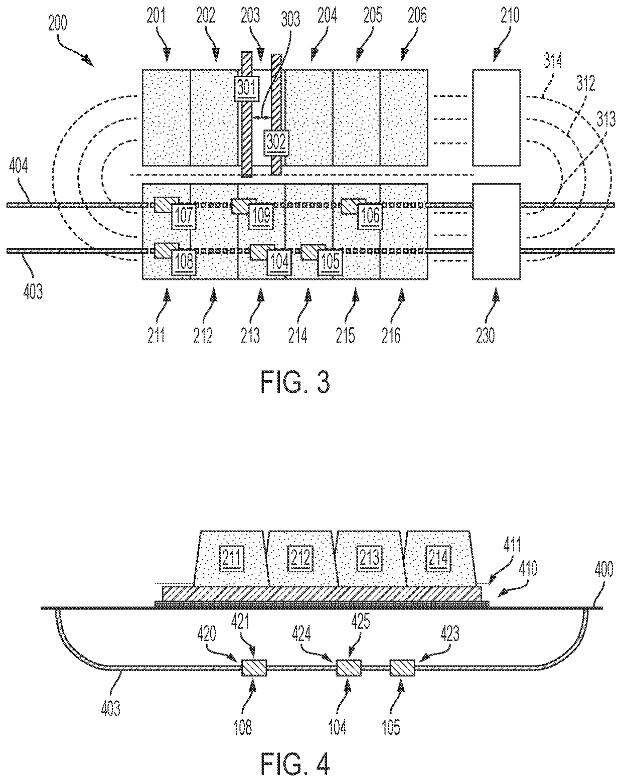
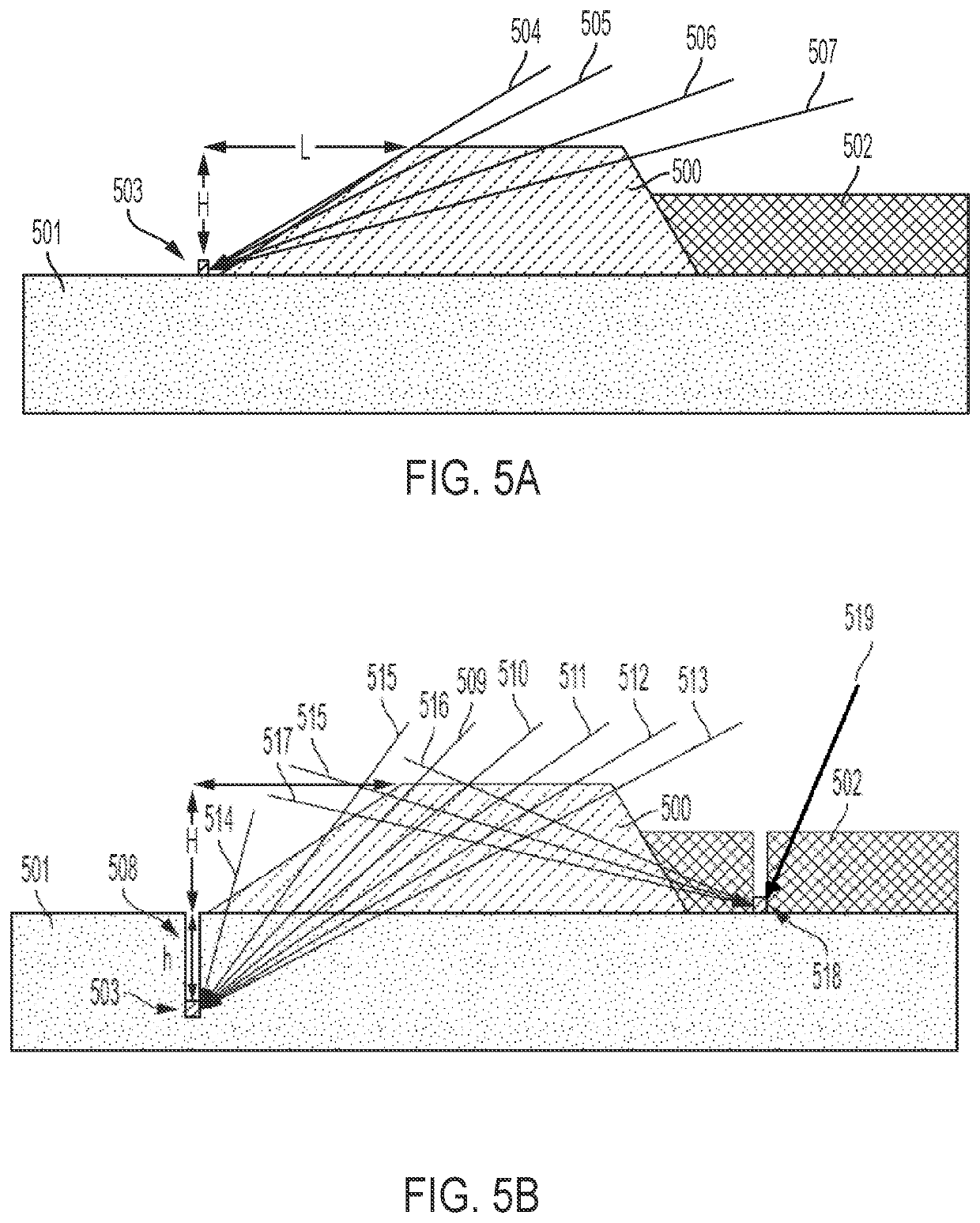
[0085]The present disclosure offers an alternative method with which to monitor slope stability as well as determine fluid volumes within a large structu...


PUM


Abstract

This disclosure relates to monitoring and assessing the mechanical stability and fluid accumulation in natural or man-made slopes comprising primarily of unconsolidated material, such as embankments, dams, roads, waste dumps, as well as man-made heaps of bulk materials that may occur in the stockpiling of grains, gravel, stones, sand, coal, cement, fly ash, salts, chemicals, clays, crushed limestone as well as heaps of mining ores, including crushed, milled and / or agglomerated ore, and run-of-mine materials.

Description

CROSS-REFERENCE TO RELATED APPLICATIONS[0001]This application claims priority to U.S. Provisional Application Ser. No. 62 / 939,156 filed on Nov. 22, 2019, the content of which is hereby incorporated by reference in its entirety.FIELD[0002]This disclosure relates to monitoring and assessing the mechanical stability and fluid accumulation in natural or man-made slopes primarily including unconsolidated material, such as embankments, dams, roads, and waste dumps. This disclosure also relates to monitoring and assessing the mechanical stability and fluid accumulation in man-made heaps of bulk materials that may occur in the stockpiling of grains, gravel, stones, sand, coal, cement, fly ash, salts, chemicals, clays, and crushed limestone. This disclosure further relates to monitoring and assessing the mechanical stability and fluid accumulation in heaps of mining ores, including crushed, milled and / or agglomerated ore. This disclosure also relates to monitoring and assessing the mechanica...

Claims


Application Information

Patent Timeline
IPC IPC(8): G01N23/2251E21B47/022
CPCG01N23/2251E21B47/022G01N2223/616G01N2223/601G01N2223/505G01N9/24G01N23/06G01N33/246G01N23/02
Inventor BOTTO, TANCREDIREPENNING, RICARDOARRAU, FRANCISCO
Owner MUON VISION INC
Learn More