Wind and wave desalination vessel

Pending Publication Date: 2021-05-20
DEHLSEN ASSOC OF THE PACIFIC LTD
View PDF0 Cites 8 Cited by
  • Summary
  • Abstract
  • Description
  • Claims
  • Application Information

AI Technical Summary

Benefits of technology

The patent describes a design for a wind turbine that reduces the risk of overturning under high wind loads and ensures a steady power output. This is achieved by offsetting the vertical axis of the turbine tower from the spar / ballast cylindrical section, which increases resistance to wind thrust loading. The design also includes downstream pontoons that further limit the backward pitching of the turbine and reduce the risk of collision with waves. The use of both wind and waves for power production provides greater reliability and flexibility for power supply planning.

Problems solved by technology

Large central RO plants require years of planning and construction, along with the need for a significant electric power supply.
An RO surface vessel may impose an undesirable view on coastline natural beauty, which is particularly unwelcome if the vessel is moored in an area dependent on tourism.
A permanently moored RO surface vessel for long-term commercial water delivery to shore is not easily moved out of harm's way.
Vessels with an extensive surface profile are especially vulnerable to high winds and wave forces.
Marine surface vessels are also subject to extreme environmental forces such as wind and waves, where pitch and roll in high seas can test survival.

Method used


Image

  • Wind and wave desalination vessel
  • Wind and wave desalination vessel
  • Wind and wave desalination vessel

Examples


Embodiment Construction

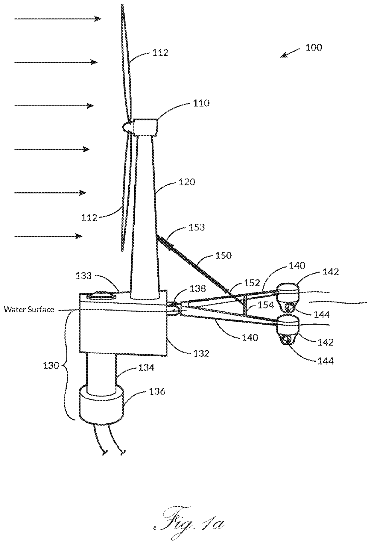
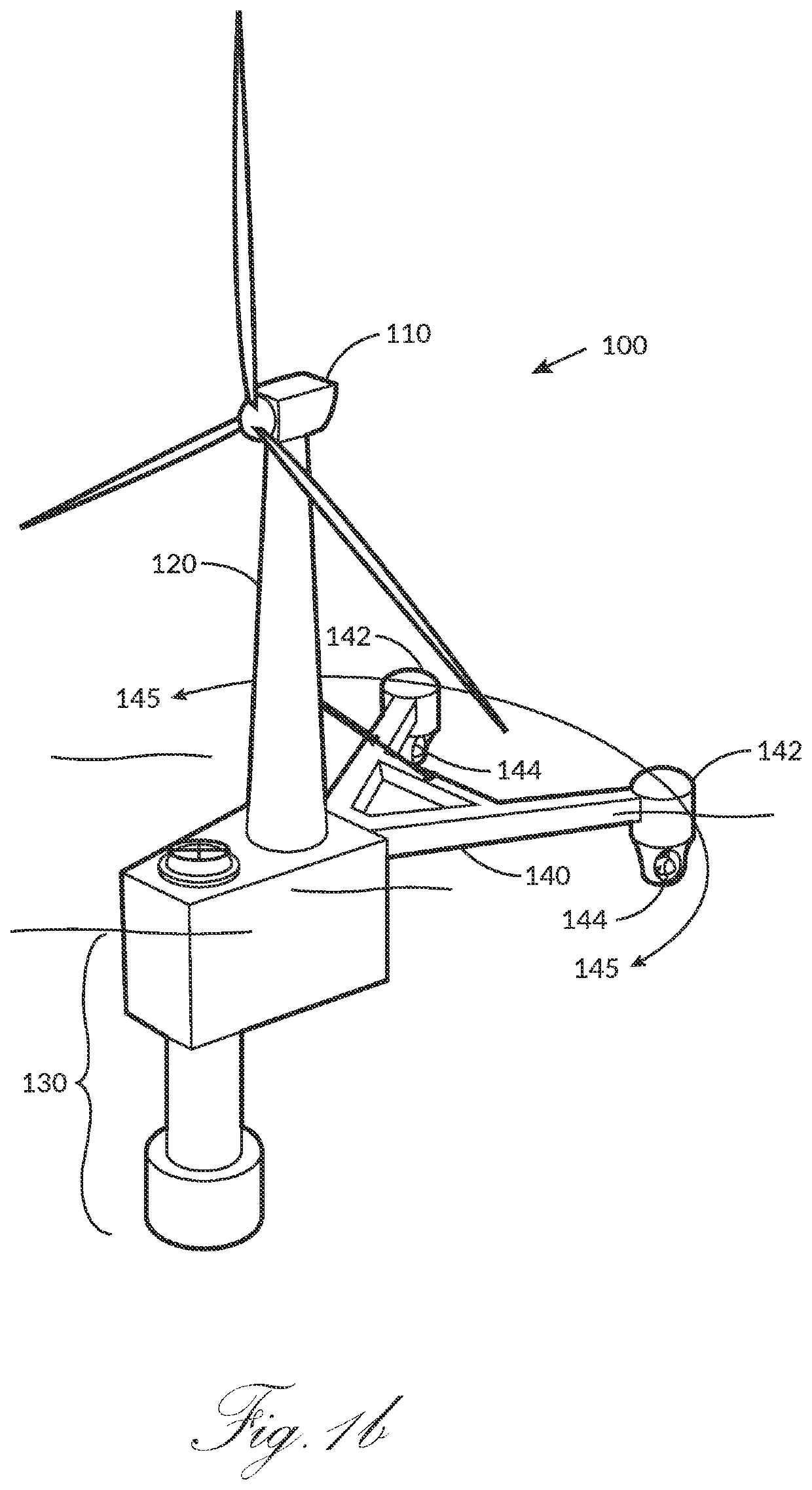
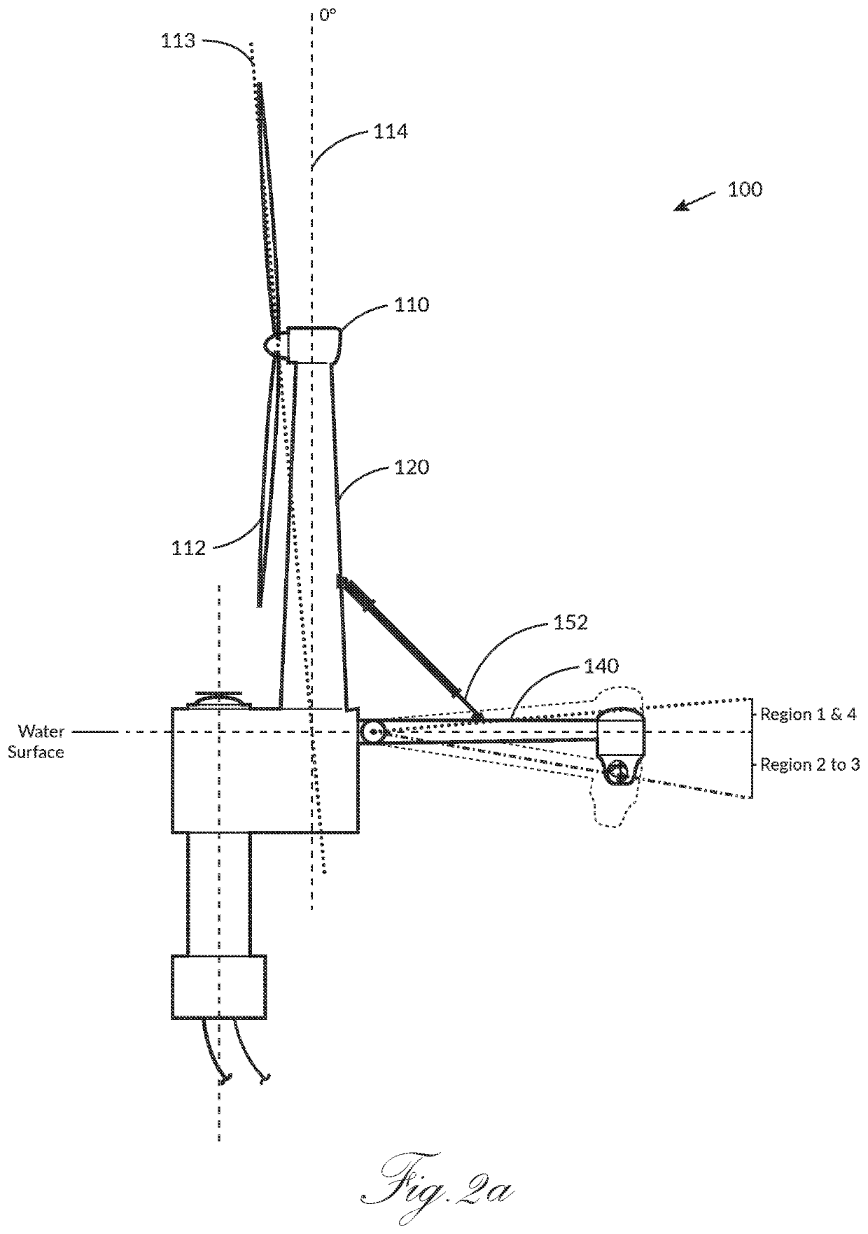
[0035]Preferred embodiments of the present invention and their advantages may be understood by referring to FIGS. 1-4, wherein like reference numerals refer to like elements. The present invention may be deployed in any water environment, preferably where one or more renewable energy sources are available. Pipeline connection to a shore-based water offtake infrastructure is required unless at-sea water delivery is available, for example, for a cruise ship water supply. Connection to an onshore electrical grid is optional.

[0036]The present invention provides a novel topology for integrating a desalination system with a renewable energy generator, such as a wind turbine on a tower mounted on top of a spar buoy. Compelling synergies result from this integration. Offshore wind turbines require high stability with minimum pitch, roll, and heave in response to sea states and must also be resistant to the wind's overturning force against the wind turbine's rotor and tower. Among other adva...


PUM


Abstract

The present invention provides a novel floating and renewable energy-powered desalination vessel, which also functions as a wind turbine generator and wave energy generator platform. With energy derived from the wind and waves, the vessel performs reverse osmosis within a vertically positioned cylindrical section extending below a buoyancy chamber. The cylindrical section contains reverse osmosis membranes located above a seawater screening and filtration system, which serve as ballast. The entire vessel and power systems are configured to have the center of mass below the center of buoyancy, forming a vertically stable floating structure with minimum pitch, roll, and wave heave in high sea states. The electric power generated is utilized internally to produce desalinated water or hydrogen from the desalinated water's electrolysis, power an onboard data center, or power delivery to a shoreside power grid. In addition to a wind turbine generator and a wave energy generator, a photovoltaic array or a marine current generator may be utilized to power these applications. Alternatively, the desalination vessel operates with the assistance of shore-based power provided by cable.

Description

CROSS-REFERENCE TO RELATED APPLICATIONS[0001]The present application is a continuation-in-part of U.S. patent application Ser. No. 17 / 087,309, entitled “Reverse Osmosis Water Production Apparatus,” and filed on Nov. 2, 2020, which claims priority to U.S. patent application Ser. No. 16 / 129,783, entitled “Reverse Osmosis Water Production Apparatus,” and filed on Sep. 12, 2018, which claims priority to New Zealand Patent Application No. 735748, filed Sep. 22, 2017, the entire disclosures of which are all incorporated by reference herein.BACKGROUND OF THE INVENTION1. Field of Invention[0002]This invention relates to floating, renewable energy-powered desalination plants.2. Description of Related Art[0003]Reverse osmosis (RO) systems for high volume seawater to freshwater production are generally land-based. RO systems are typically implemented as either a large central plant near the coast or a smaller system, packaged in a shipping container type enclosure. Both types draw seawater int...

Claims


Application Information

Patent Timeline
IPC IPC(8): B01D61/08B01D61/02B01D61/10B01D63/06C02F1/44B63B43/06B63B1/04B63B77/00
CPCB01D61/08B01D61/022B01D61/025B01D61/10B01D63/06C02F1/441C02F2103/08B63B1/048B63B77/00C02F2307/00B01D2313/06B01D2317/04B01D2317/06B63B43/06B01D2313/20C02F2201/007C02F2201/008C02F2303/10Y02W10/30Y02W10/33B63B2035/446B63B2001/145B63B43/14B01D2313/36C02F2201/009Y02A20/212Y02A20/144B01D2313/367B01D2313/54B01D2315/06B63B2043/047B63B2035/442B63B39/03B63B2001/044B63B1/107B01D61/026B01D2313/206B01D2313/57B01D61/081
Inventor DEHLSEN, JAMES GEORGE PURNELL
Owner DEHLSEN ASSOC OF THE PACIFIC LTD
Why Eureka
Try Eureka