
Railway vehicle power bogie having a semi-suspended motor

Active Publication Date: 2010-12-09
ALSTOM TRANSPORT TECH SAS
View PDF22 Cites 10 Cited by
  • Summary
  • Abstract
  • Description
  • Claims
  • Application Information

AI Technical Summary

Benefits of technology

[0011]One of the objects of the invention is to remedy those disadvantages by proposing a compact bogie of reduced mass, which has limited non-suspended masses and a simple drive for a powerful motor.
[0013]The space freed in the transverse direction by integrating the reducing gear in the axle box accordingly allows a powerful motor to be accommodated between the wheels of the bogies with a type of drive which on the one hand allows the non-suspended masses to be limited, relative to a solution with a semi-suspended motor, and on the other hand facilitates mounting, as compared with a fully suspended motor.
[0024]Such an articulated chassis allows the bogie to travel over defects in the tracks—or “distortions”—without incident, by allowing the bogie to have points of support on the ground which are not in the same plane without excessive weight transfers, which increase the risks of derailment of the vehicle. The rolling movement is accordingly absorbed by the articulation of the bogie chassis.

Problems solved by technology

This transmission is simple to implement but has high non-suspended masses, which limits the speed of the vehicle.
This transmission increases the space requirement of the bogie in the direction of travel of the vehicle.
This solution allows the vehicle to travel at high speeds but it is complex to implement because it requires a hollow bearing at the output of the reducing gear, connections between that bearing and the hollow shaft on the reducing gear side as well as between the axle and the hollow shaft.
In the case of a power bogie having an interior chassis, there is little space in the transverse direction to accommodate a powerful and bulky motor.
The only solution of the prior art which allows a powerful motor, and the associated transmission, to be accommodated, while limiting the non-suspended masses, is hollow-shaft suspension, which is complex to implement, as described above.

Method used


Image

  • Railway vehicle power bogie having a semi-suspended motor
  • Railway vehicle power bogie having a semi-suspended motor
  • Railway vehicle power bogie having a semi-suspended motor

Examples


Embodiment Construction

[0030]In the description, the terms “vertical” and “horizontal” are defined relative to a bogie mounted in a railway vehicle. Accordingly, a horizontal plane is substantially parallel to the plane in which the axles extend, and the vertical plane is substantially parallel to the plane in which the wheels extend. The term “longitudinal” is defined relative to the direction in which a railway vehicle extends in a horizontal plane, and the term “transverse” is defined in a direction substantially perpendicular to the longitudinal direction in a horizontal plane.

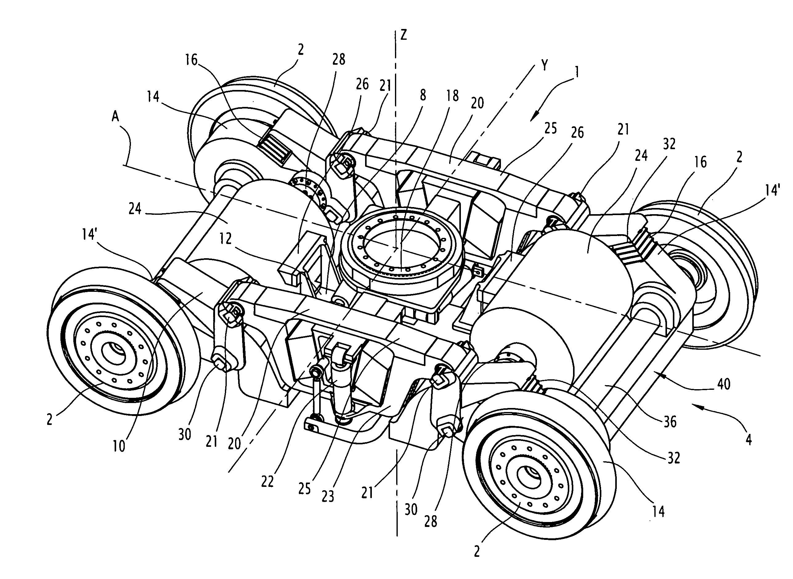
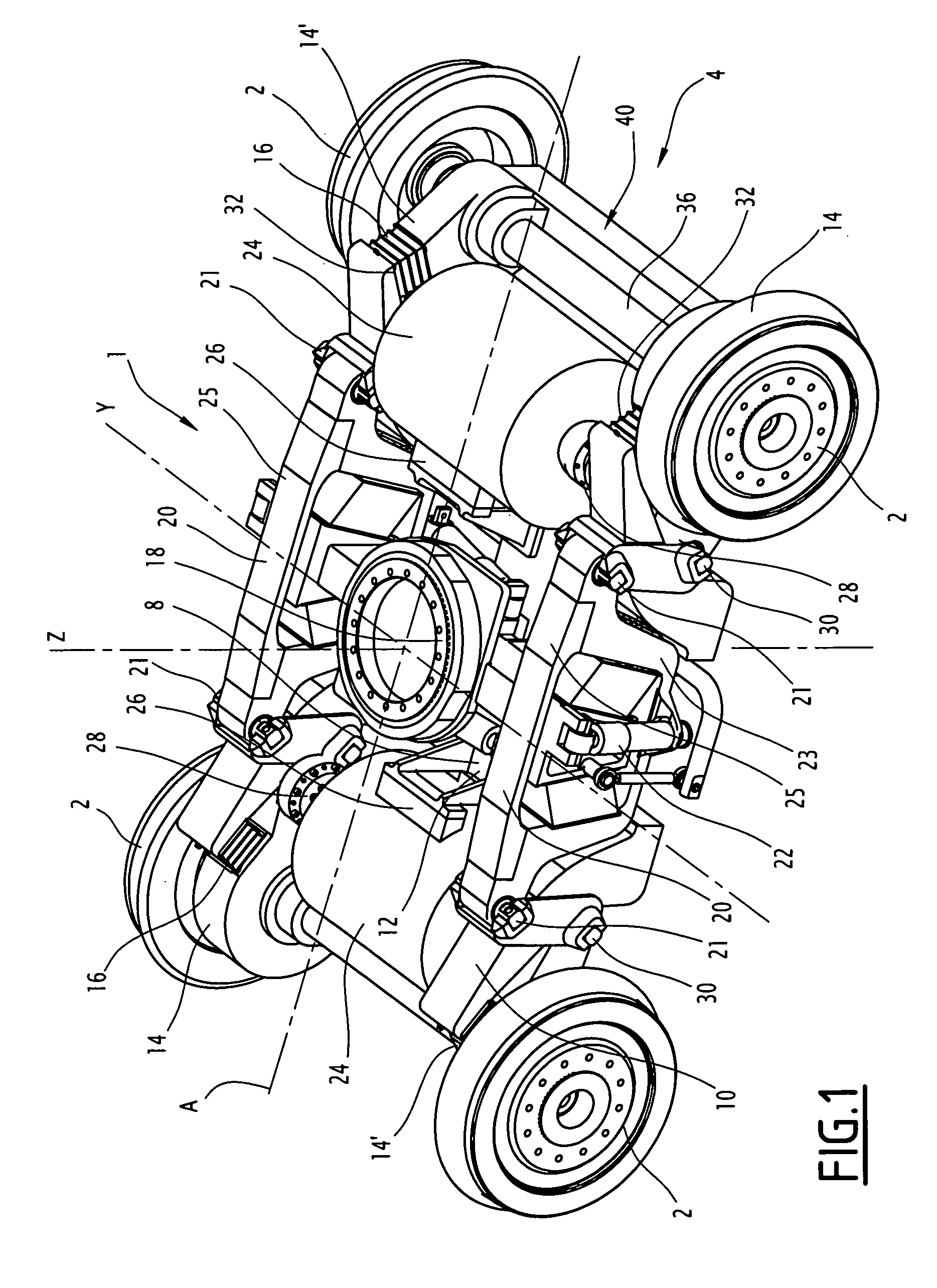
[0031]With reference to FIG. 1, a motorized bogie 1 of a railway vehicle (not shown), for example a subway vehicle, is described.

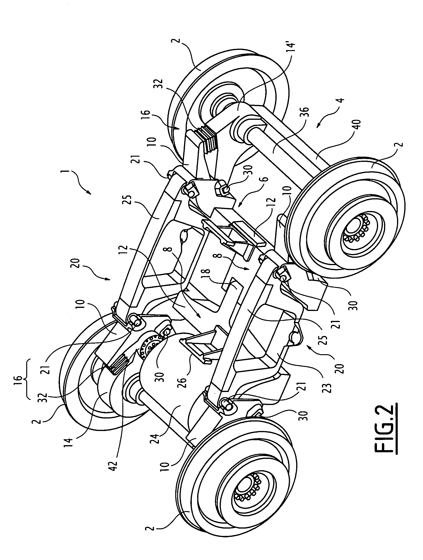
[0032]The bogie 1 comprises two pairs of wheels 2, the wheels 2 of each pair being connected to one another by a shaft 36 to form an axle 4. The axles 4 are connected to one another by a chassis 6 (see FIG. 2), called an interior chassis, which comprises two half-chasses 8 each integral with an axle 4....


PUM


Abstract

A bogie includes two pairs of wheels (2), the wheels (2) of one pair being connected to one another by a shaft to form an axle (4), the axles (4) being connected to one another by a chassis (6) having at least two side members (10) resting on axle boxes (14, 14′) of each axle (4). The boxes (14, 14′) are arranged between the wheels (2) of the axle (4), and a motor (24) fixed to the chassis (6) extends between the wheels (2) of the axle (4) and drives the axle (4) in rotation by way of a coupling (42) and a reducing gear (28). One of the axle boxes (14) accommodates the reducing gear (28) of the motor (24).

Description

[0001]This claims the benefit of French Patent Applicaiton FR 09 53728, filed Jun. 5, 2009 and hereby incorporated by reference herein.FIELD OF THE INVENTION[0002]The present invention relates to a motorized bogie for a railway vehicle, of the type comprising two pairs of wheels, the wheels of one pair being connected to one another by a shaft to form an axle, said axles being connected to one another by a chassis having at least two side members resting on axle boxes of each axle, said boxes being arranged between the wheels of said axle, a motor fixed to the chassis extending between the wheels of the axle and driving said axle in rotation by way of a coupling and a reducing gear.[0003]The invention relates also to a railway vehicle comprising such a bogie.BACKGROUND[0004]In a railway vehicle, each motorized bogie is provided with means for driving each axle in rotation. The drive means comprise at least one motor, at least one reducing gear, and a mechanical device for transmitti...

Claims


Application Information

Patent Timeline
IPC IPC(8): B61C9/38
CPCB61F3/04B61C9/44B61C9/50B61F5/24B61F5/38
Inventor RODET, ALAIN
Owner ALSTOM TRANSPORT TECH SAS
Learn More