Platform fracture fixation implants
a technology for fixing implants and fractures, which is applied in the field of implants for fixing fractures on platforms, can solve the problems of affecting the ability of trauma-recovery treatment providers to reliably treat trauma injuries, and affecting the rate and probability of fracture healing over tim
- Summary
- Abstract
- Description
- Claims
- Application Information
AI Technical Summary
Benefits of technology
Problems solved by technology
Method used
Image

Examples
first embodiment
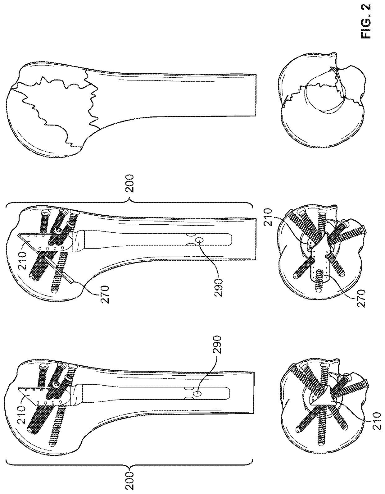
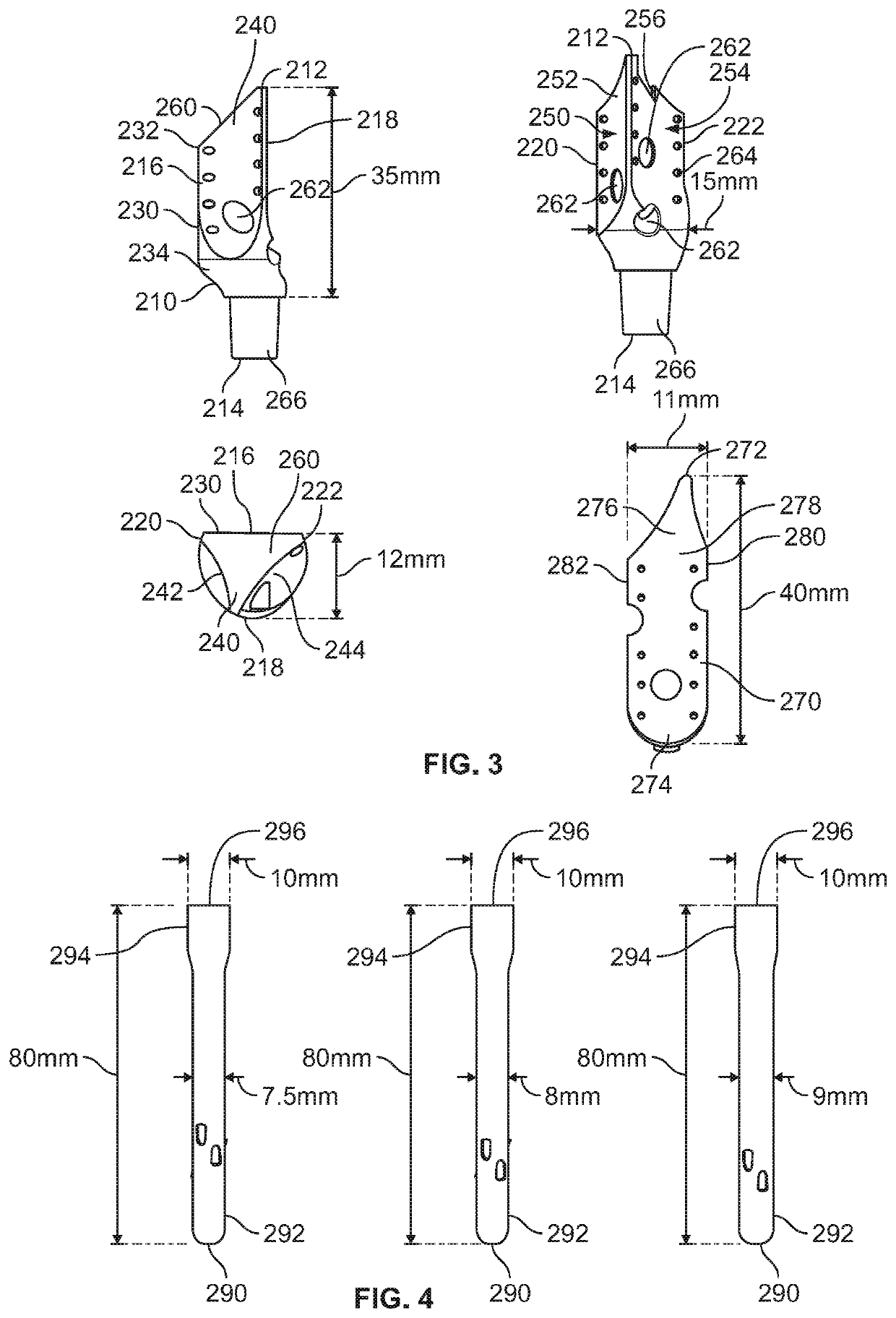
[0050]FIG. 3 shows a detailed view of a proximal portion 210 of an implant that is used in the implant 200 of FIG. 2. FIG. 3 includes dimensional measurements for various portions of the proximal portion 210 shown therein, but it will be apparent to those of skill in the art that these are only exemplary dimensions and that the proximal portion 210 of FIG. 3 may be provided in various sizes. In some embodiments, the proximal portion 210 includes a proximal end 212, a distal end 214, a medial side 216, a lateral side 218, an anterior edge 220, and a posterior edge 222. In some embodiments, the proximal portion 210 includes a medial surface 230 having a proximal end 230 and a distal end 232.
[0051]In an embodiment, a proximal portion 210 includes an asymmetric body to facilitate tuberosity reconstruction. In an embodiment, an anterior support surface 250 is provided for the lesser tuberosity, posterior support surface 254 is provided for the greater tuberosity, and the protrusion 240 s...
fifth embodiment
[0064]FIG. 14 shows multiple views of a proximal portion 1362 that may form the proximal portion of the implant of FIG. 13. In some embodiments, the proximal portion 1310 includes a proximal end 1312, a distal end 1314, a medial side 1316, a lateral side 1318, an anterior end 1320, and a posterior end 1322. As noted above, the cephlalomedullary proximal portion of FIG. 14 is asymmetric and is therefore more rotationally stable than a cylinder for improved tuberosity reconstruction. The locations 1362 for attachment of the screws are distributed throughout the proximal portion and suture holes 1364 are provided to aid in the bone reattachment. The proximal portion 1310 of FIG. 14 includes a medial support 1370 to provide improved humeral head support in the case of medial calcar disruption.
sixth embodiment
[0065]In some embodiments, a proximal humeral nail and a locking plate are used in conjunction with one another. Such embodiments may be suitable for use to repair severe and multipart comminuted fractures. In some embodiments of a modular platform fracture fixation implant, this combination can be accomplished by providing multiple sizes of a proximal nail portion in any of the aforementioned configurations while ensuring the central lag is centered in the humeral head, with the plate positioned ideally on the lateral humerus, and achieving a sufficient distribution of screws into the fractured bone. FIG. 15 illustrates various views of a platform fracture fixation implant 1500 having a proximal portion 1510, which is combined with a locking plate 1511. A four-part fracture of the proximal humerus is shown on the right for reference. In the embodiment of FIG. 15, the locations for screw attachment are spread from the central axis in order to better distribute the screws through the...
PUM
 Abstract
Description
Claims
Application Information
 - R&D
- Intellectual Property
- Life Sciences
- Materials
- Tech Scout
- Unparalleled Data Quality
- Higher Quality Content
- 60% Fewer Hallucinations
Browse by: Latest US Patents, China's latest patents, Technical Efficacy Thesaurus, Application Domain, Technology Topic, Popular Technical Reports.
© 2025 PatSnap. All rights reserved.Legal|Privacy policy|Modern Slavery Act Transparency Statement|Sitemap|About US| Contact US: help@patsnap.com