Quick fastening device

Pending Publication Date: 2021-04-22
UNIWISDOM TECH (SUZHOU) CO LTD
View PDF2 Cites 0 Cited by
  • Summary
  • Abstract
  • Description
  • Claims
  • Application Information

AI Technical Summary

Benefits of technology

The invention allows for a smooth and smooth operation of an impact unit by reducing friction and wear. The planetary gear and connecting rod module rotate relative to each other, ensuring a straight line trajectory and minimizing friction force. This results in a speedy release of the driving mechanism, stability, and smooth operation of the impact unit, improving work quality and market competitiveness.

Problems solved by technology

However, in the process of motion when such a structure encounters a force, it will produce a large deflection angle, that is, the swing angle of the connecting rod.
If the deflection angle is too large, the friction force of the load (impact unit) in motion will be increased and cause the mechanism to wear out, resulting in the service life of the product not guaranteed.
How to make the driving mechanism after compressing the energy storage medium release quickly has become a difficulty in the design of such mechanical equipment.

Method used


Image

  • Quick fastening device
  • Quick fastening device
  • Quick fastening device

Examples


Embodiment Construction

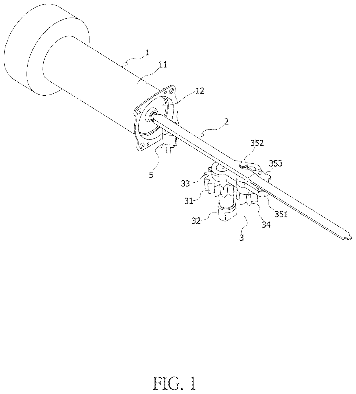
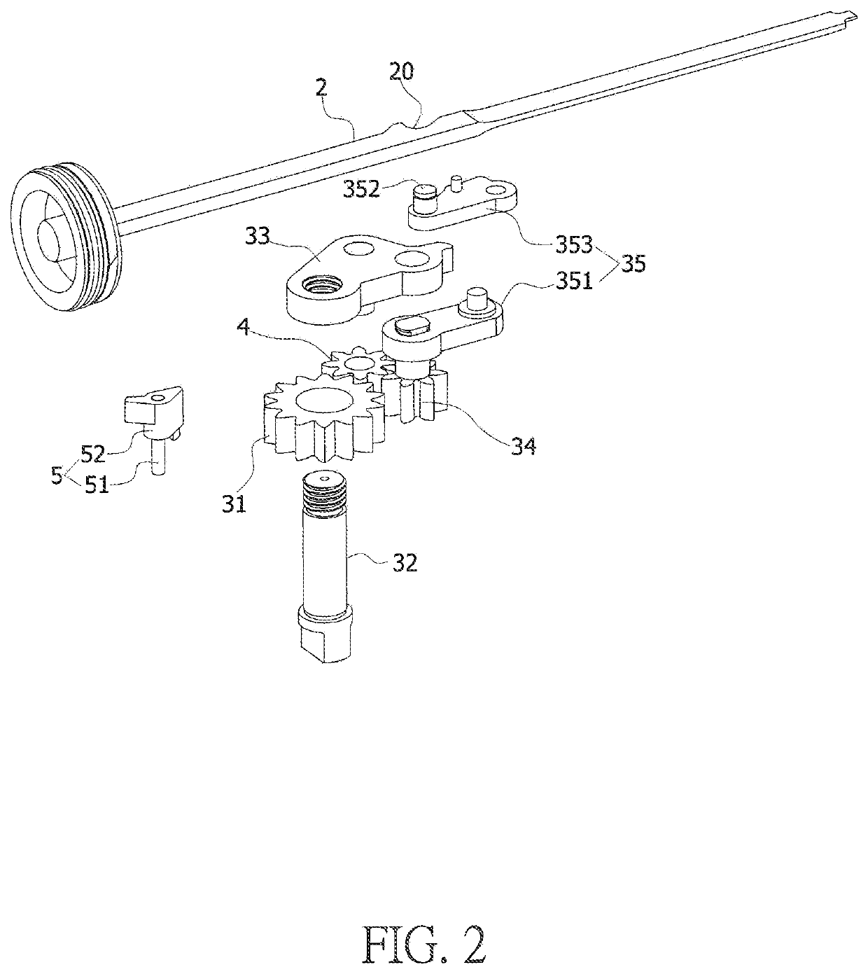
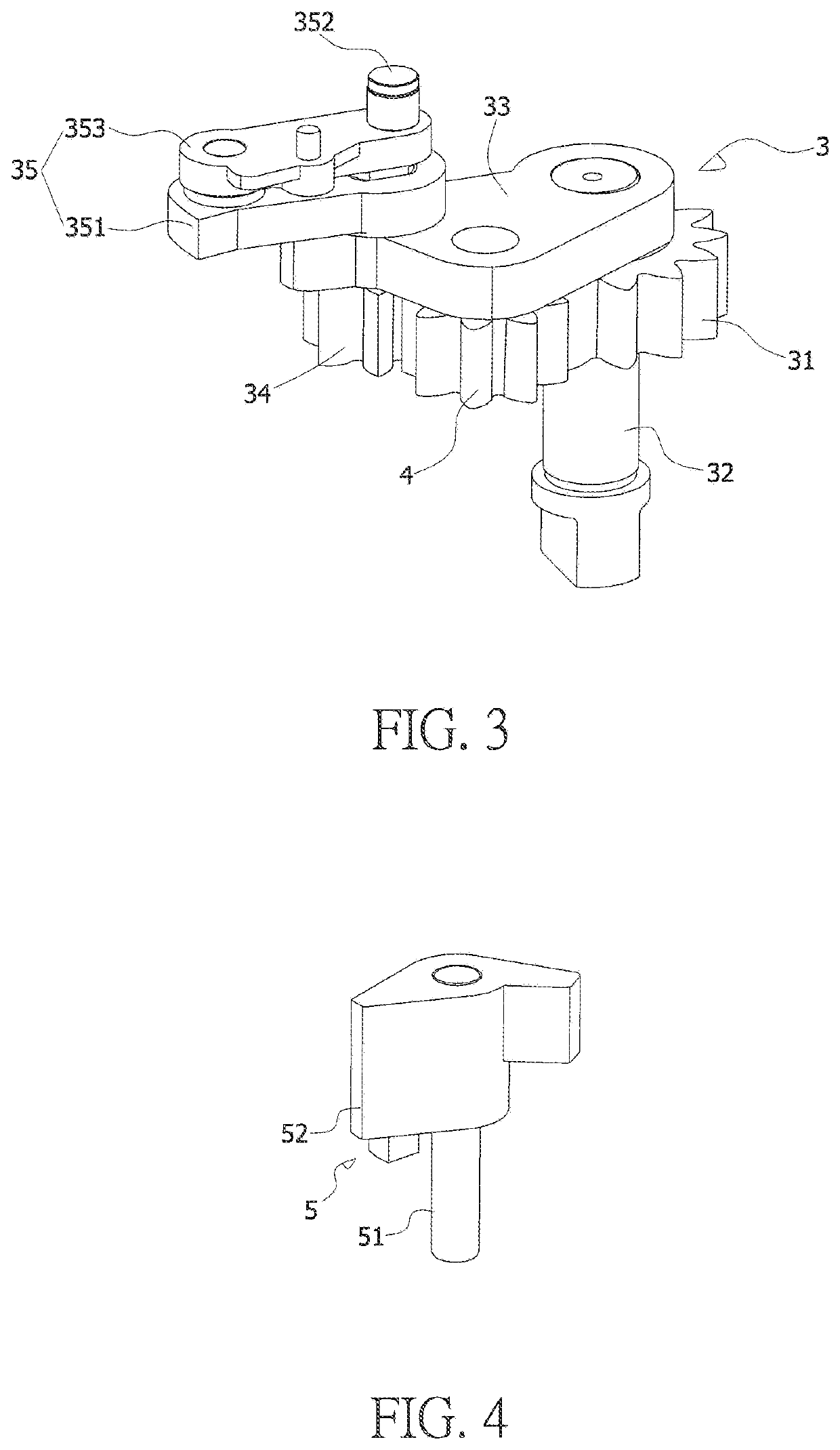
[0064]As shown in FIGS. 1-8, and 10-15, it is a quick fastening device, which comprises an energy storage medium 1, an impact unit 2 connected to the energy storage medium 1, and a driving mechanism 3 for pushing the impact unit 2 to compress the energy storage medium 1 for energy storage.

[0065]The impact unit 2 and the driving mechanism 3 are all installed on a base (not shown in the figure).

[0066]The energy storage medium 1 is used to be compressed for storing energy and then releasing the energy to do work to the outside and driving the impact unit 2 to achieve impact working.

[0067]The energy storage medium comprises any medium that can be compressed to store energy and then expanded to do external work, such as gas, spring, rubber, and various elastomers. In the embodiment, the energy storage medium comprises a cylinder body 11 and air stored in it, and the impact unit 2 is connected to the piston 12 in the cylinder body 11. When the driving mechanism 3 drives the impact unit 2 ...


PUM


Abstract

A quick fastening device, which comprises an energy storage medium, an impact unit, and a driving mechanism; the driving mechanism comprises a fixed sun gear, an output shaft not linked to the sun gear, a crank fixed on the upper end of the output shaft, a planetary gear installed on the crank in a spinning manner and capable of revolving around the sun gear as the crank rotates, and a connecting rod module mounted on the upper end of the planetary gear and connected to the impact unit. A linkage element is arranged between the planetary gear and the sun gear for driving the planetary gear to rotate in a direction opposite to the direction in which the planetary gear revolves relative to the sun gear.

Description

BACKGROUND OF INVENTION1. Field of the Invention[0001]The present invention relates to the technical field of mechanical tool products, in particular to a quick fastening device.2. Description of Related Art[0002]For a quick fastening machine (e.g., a nail gun), it is usually necessary to compress an energy storage medium (e.g., gas, spring, and rubber, etc.) to store energy, and then quickly release it to do work to the outside.[0003]In addition, the common driving mechanism converts a rotational motion into a reciprocating motion, and its structure is a crank-connecting rod structure. However, in the process of motion when such a structure encounters a force, it will produce a large deflection angle, that is, the swing angle of the connecting rod. If the deflection angle is too large, the friction force of the load (impact unit) in motion will be increased and cause the mechanism to wear out, resulting in the service life of the product not guaranteed.[0004]How to make the driving...

Claims


Application Information

Patent Timeline
IPC IPC(8): B25C1/04F16H19/02F16H19/06
CPCB25C1/047F16H2019/0686F16H19/0622F16H19/02B25C1/06
Inventor XU, YING
Owner UNIWISDOM TECH (SUZHOU) CO LTD
Why Eureka
Try Eureka