
Kit of parts of track and plug

Active Publication Date: 2021-04-15
SIGNIFY HLDG BV
View PDF4 Cites 0 Cited by
  • Summary
  • Abstract
  • Description
  • Claims
  • Application Information

AI Technical Summary

Benefits of technology

The patent describes an elongated track connector kit that allows for easy mounting and rotation of plugs and modules in different directions. The connector portion has asymmetric patterns or a mount feature on its surfaces for easy mounting of add-ons. The kit also includes at least two electric conductors that can be short-circuited if they touch. The main benefit of this kit is that it allows for convenient and flexible mounting of track without the need for spacing or mounting hardware. Moreover, it allows for easy installation and use of various types of modules like lighting, internet, occupancy monitoring, and safety enhancement.

Problems solved by technology

However, this involves both the risk of a power overload of the track with subsequent risk of overheating and early failure, and involves the risk of connecting plugs with reversed polarity for said DC tracks.
When transformed to low voltage systems, this known power distribution system has yet the disadvantage that only one plug can be provided which often is insufficient to provide all of the plurality of mounted modules with enough power.

Method used


Image

  • Kit of parts of track and plug
  • Kit of parts of track and plug
  • Kit of parts of track and plug

Examples


first embodiment

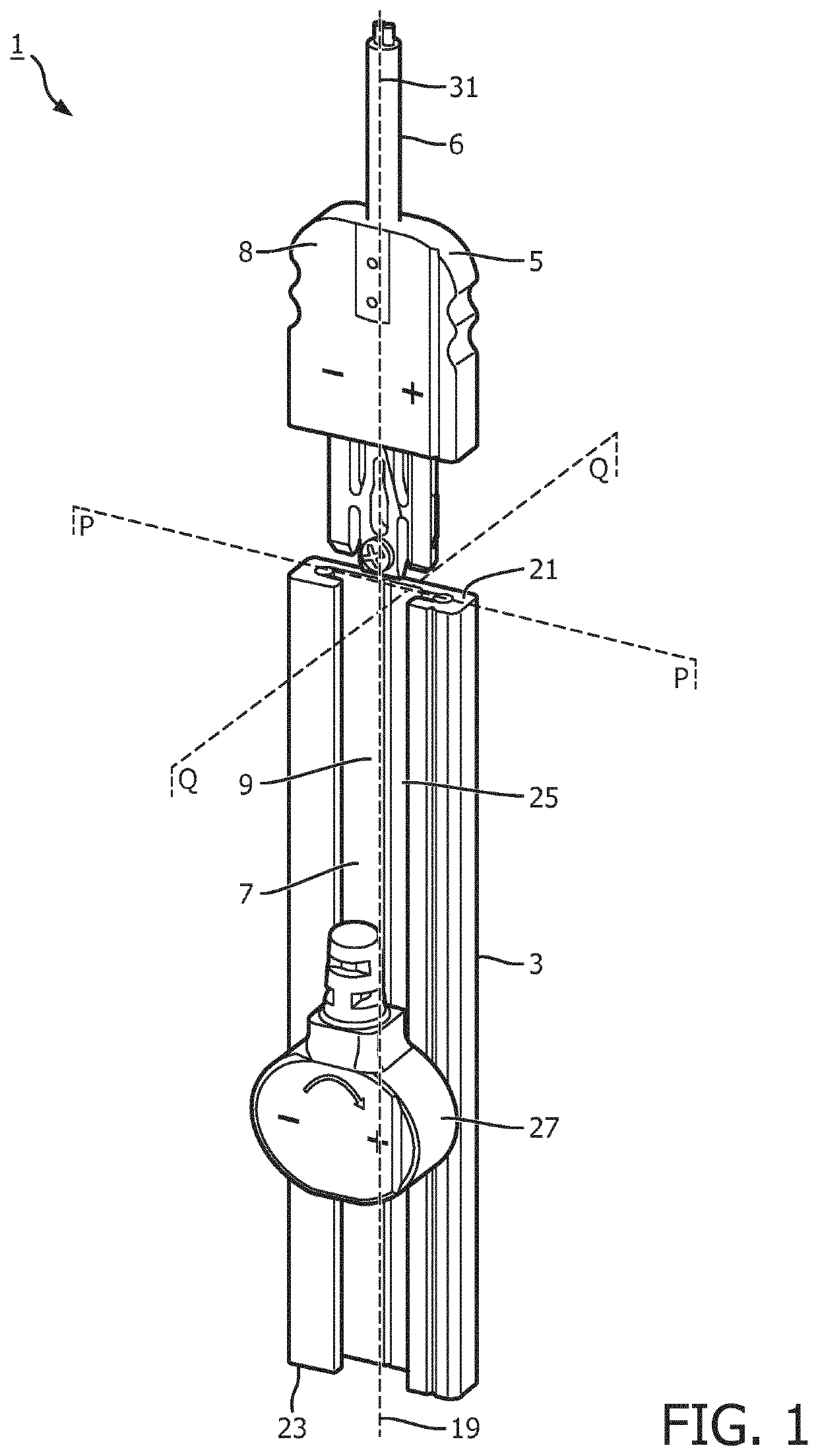
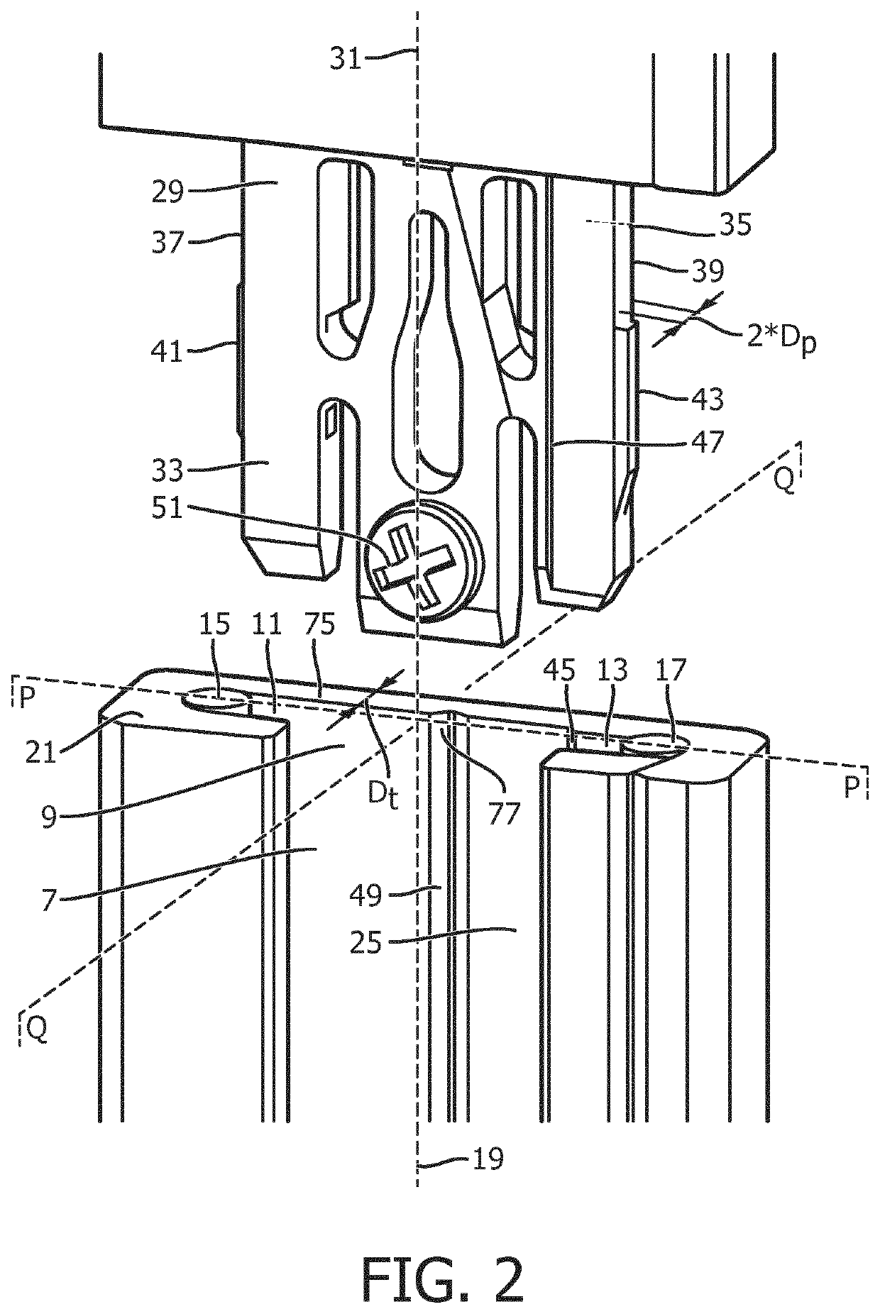
[0032]FIG. 1 shows a perspective general view of first embodiment of DC, low voltage power system comprising a kit of parts 1 according to the invention, of which FIG. 2 shows a local perspective more detailed view. The kit of parts comprises an elongated track 3 and at least one plug 5 connected via a main body 8 and an electric cable 6 of the plug to an external / remote power source (not shown). The track extends along a length axis 19 and comprises an elongated slot 7 having an open side 25 and is formed by a central groove 9 and a lateral groove 11, 13 on either side of the central groove. Each lateral groove accommodating a respective electric current conductor 15,17. The elongated track has a first end 21 and a second end 23, the slot, the open side, the grooves, and the current conductors all extend from the first end to the second end. Via the open side a single module 27 is mounted on the elongated track. The module in the FIG. 1 is an LED module, but this can alternatively ...

second embodiment

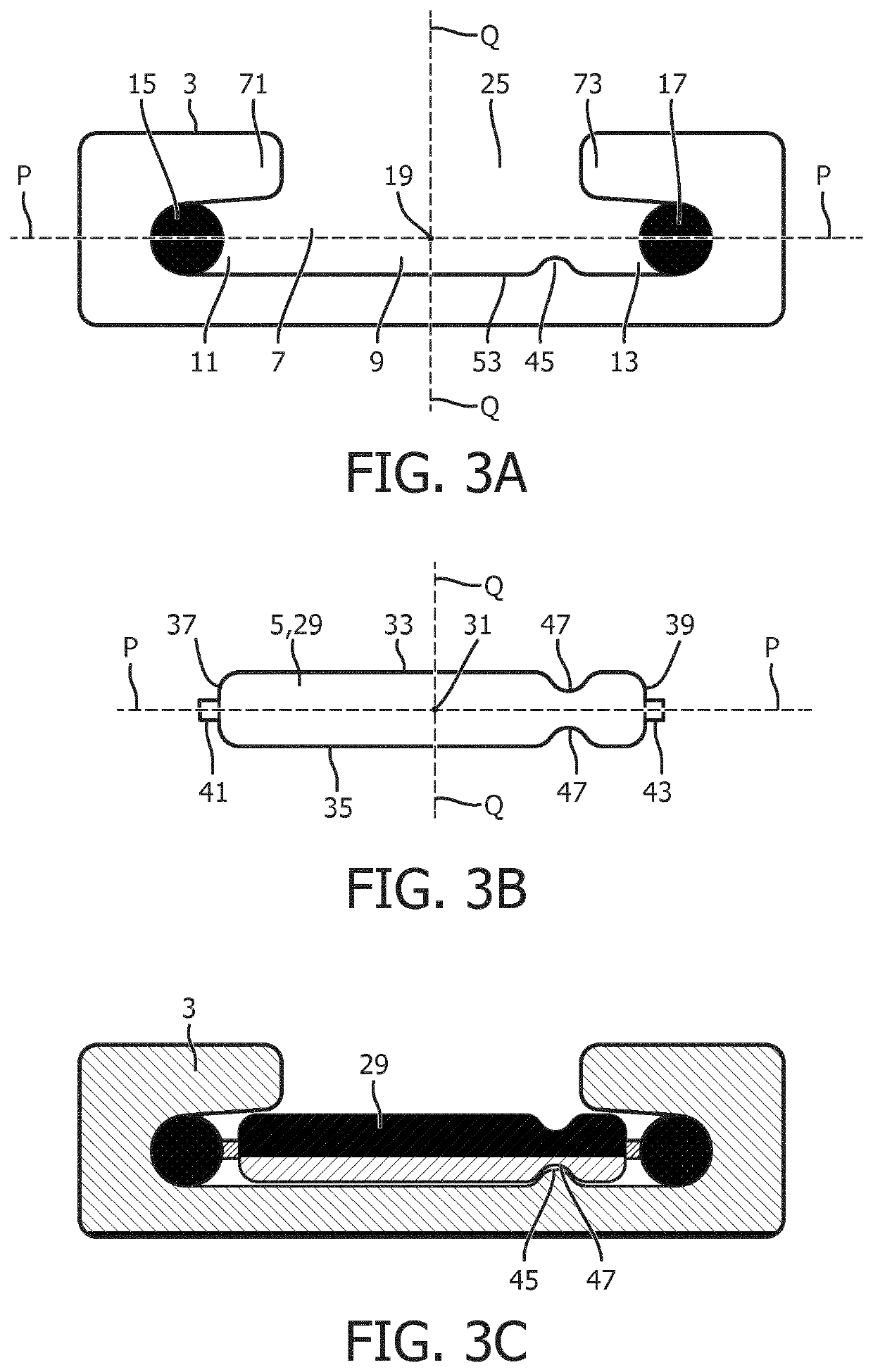
[0035]FIGS. 3A-E shows a cross sectional view of parts of the kit of parts according to the invention. FIG. 3A shows a slot cross section of the elongated track 3 in which the central groove 9 is provided with a protruding ridge as the profiled structure 45 extending along the length axis 19 and in an asymmetrical location with respect to plane Q over a bottom surface 53 of the slot 7 opposite the open side 25 of the slot. On either side of the central groove a lateral groove 11, 13 accommodating a respective electric current conductor 15, 17, is provided. Respective lips 71, 73 extend over a respective lateral groove narrowing the size of the open side and reducing the risk on unintentional touching the electrical conductors by users. The slot cross section is asymmetrical with respect to both plane P and plane Q.

[0036]FIG. 3B shows the connector cross section of the connector portion 29 of the plug 5, matching in shape with the slot cross section shown in FIG. 3A, i.e. in that the...


PUM


Abstract

The invention relates to a kit of parts comprising DC, low voltage system of an elongated track and a plug. The elongated track has a first and a second end and comprises an elongated slot formed by a central groove with at least one shielded lateral groove, both grooves lying in a plane P. Typically two electric conductors are accommodated in said at least one lateral groove. A connector portion of the plug having a connector cross section which matches with a cross section of the slot. Both said slot cross section and connector cross section are asymmetrical with respect to a plane Q extending over the length axis perpendicular to plane P, and at least one of the slot cross section and connector cross section is mirror symmetrical with respect to said plane P. The symmetric and asymmetric requirements posed on both the cross section of the elongated track and the connector portion of the plug ensure that the connector portion only being insertable into the first end in the axial direction and, after a rotation of 180° over its connector axis, only being insertable in the axial direction into the second end of said track, with maintenance of the correct polarity The invention further relates to a plug suitable for use in the kit of parts according to the invention.

Description

FIELD OF THE INVENTION[0001]The invention relates to a kit of parts comprising an elongated track and a plug. The invention further relates to a plug of said kit of parts.BACKGROUND OF THE INVENTION[0002]In particular such a kit of parts is related to an electrical power track system for lighting purposes, such as a minitrack system being of direct current (DC) thus having a specific polarity, and being of low voltage, e.g. 24 Volt or 12 Volt. These tracks find wide application for distribution of power, for example in domestic appliances, such as a room of a house, or in professional environments such as offices and / or shop windows. Via plugs, the track can be connected to power means for providing power to a single module or a plurality of energy consuming modules mountable on said track. Often the provision of a plurality of plugs is done to provide all of the plurality of mounted modules with power. However, this involves both the risk of a power overload of the track with subse...

Claims


Application Information

Patent Timeline
IPC IPC(8): H01R25/14H01R24/28H01R13/64
CPCH01R25/145H01R2103/00H01R13/64H01R24/28H01R13/642H01R25/162H01R33/06H01R2107/00
Inventor VAN DOMMELEN, MARK JOSEPHUS LUCIEN MARIAVAN KEMPEN, FRANK WALTERUS FRANCISCUS MARIE
Owner SIGNIFY HLDG BV
Learn More