Method and device for connecting parts of an exhaust gas system
- Summary
- Abstract
- Description
- Claims
- Application Information
AI Technical Summary
Benefits of technology
Problems solved by technology
Method used
Image
Examples
Embodiment Construction
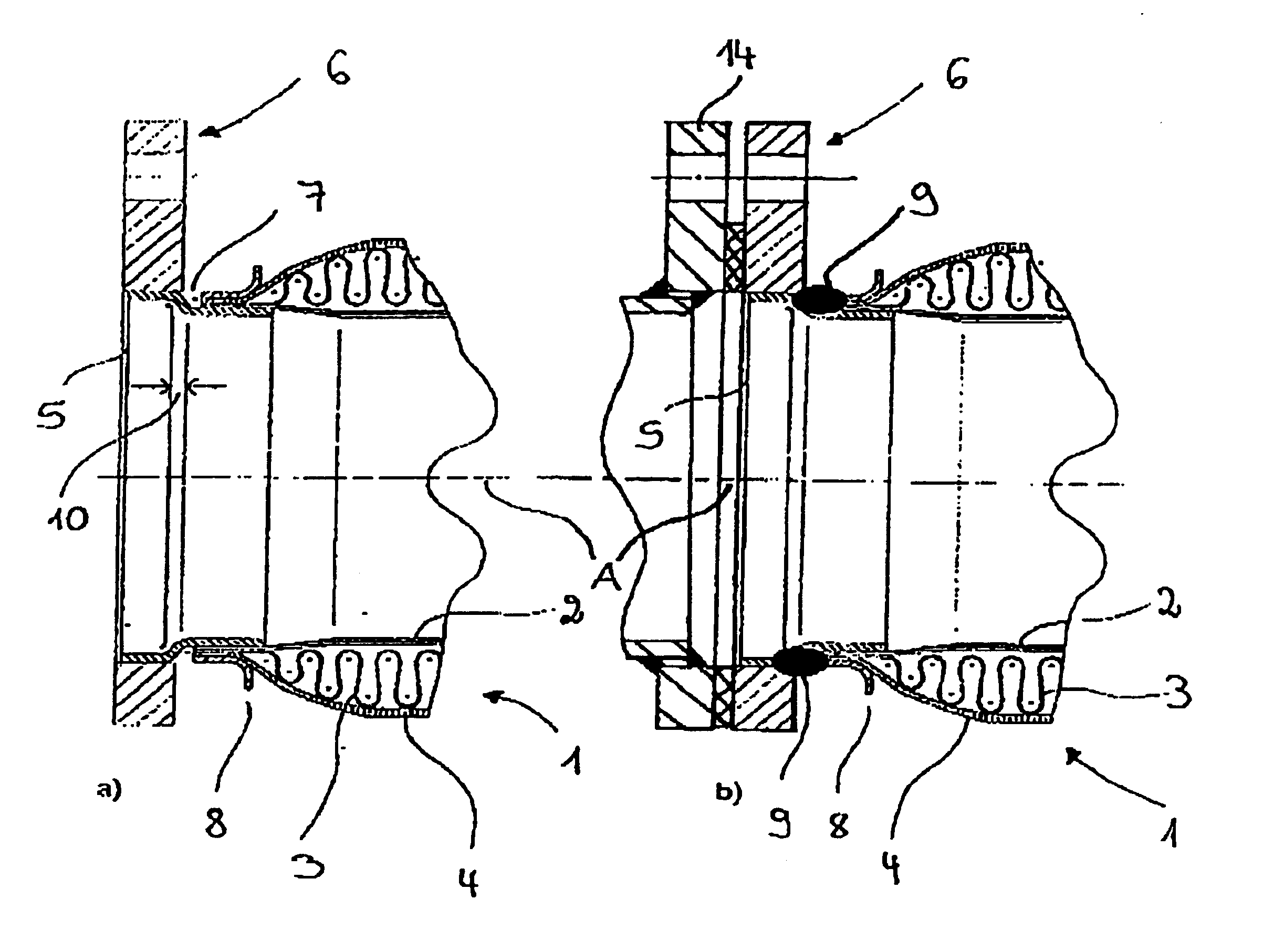
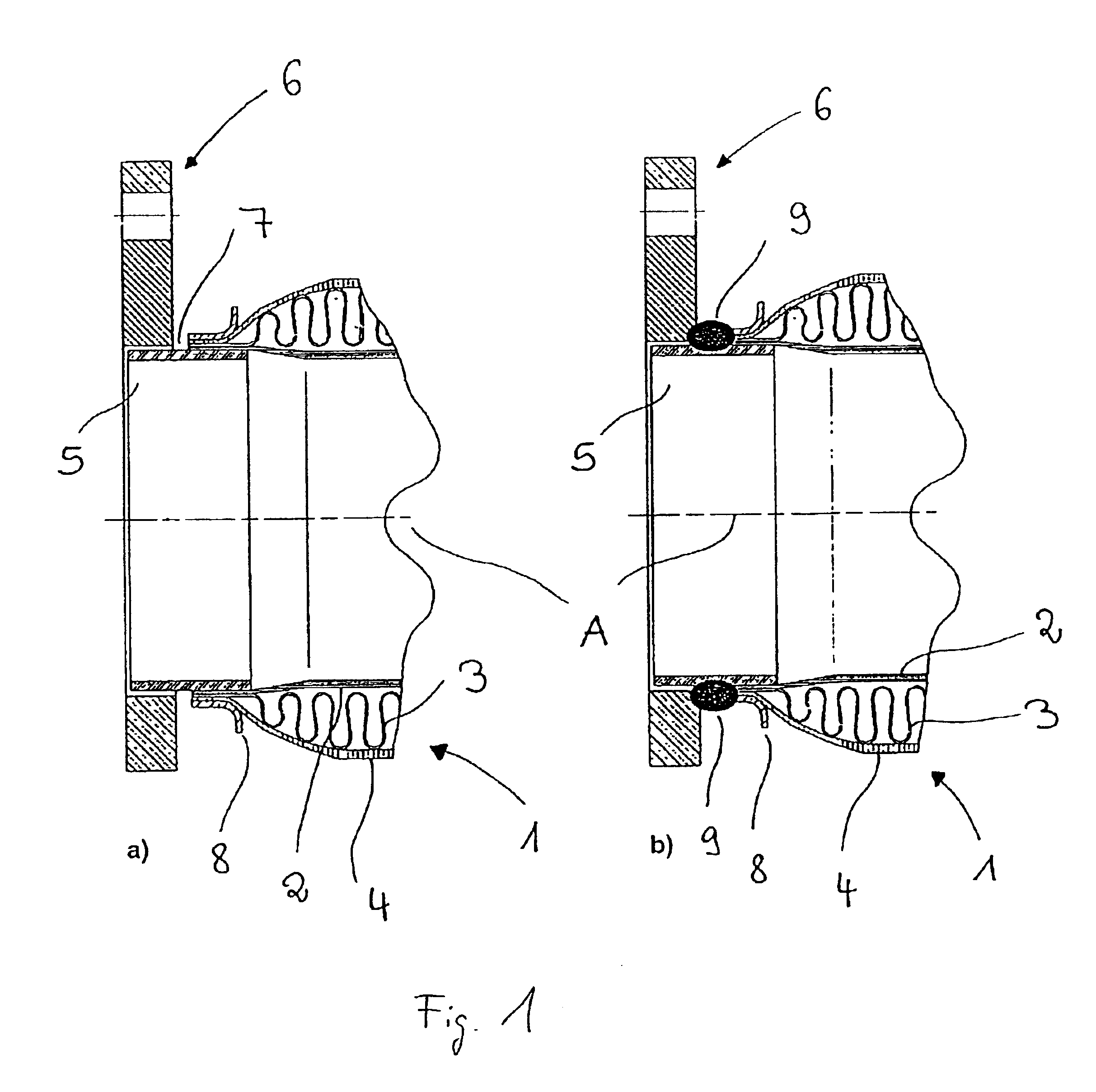
[0030]FIG. 1 shows a sectional view, in a plane perpendicular to tube axis A, of a connection between parts of an exhaust gas system produced by means of the inventive method.
[0031]In the embodiment shown, the metal tube 1 comprises an agraff-inliner 2, a metal bellows 3 and an outer woven jacket 4 disposed coaxially, radially from the inside towards the outside.
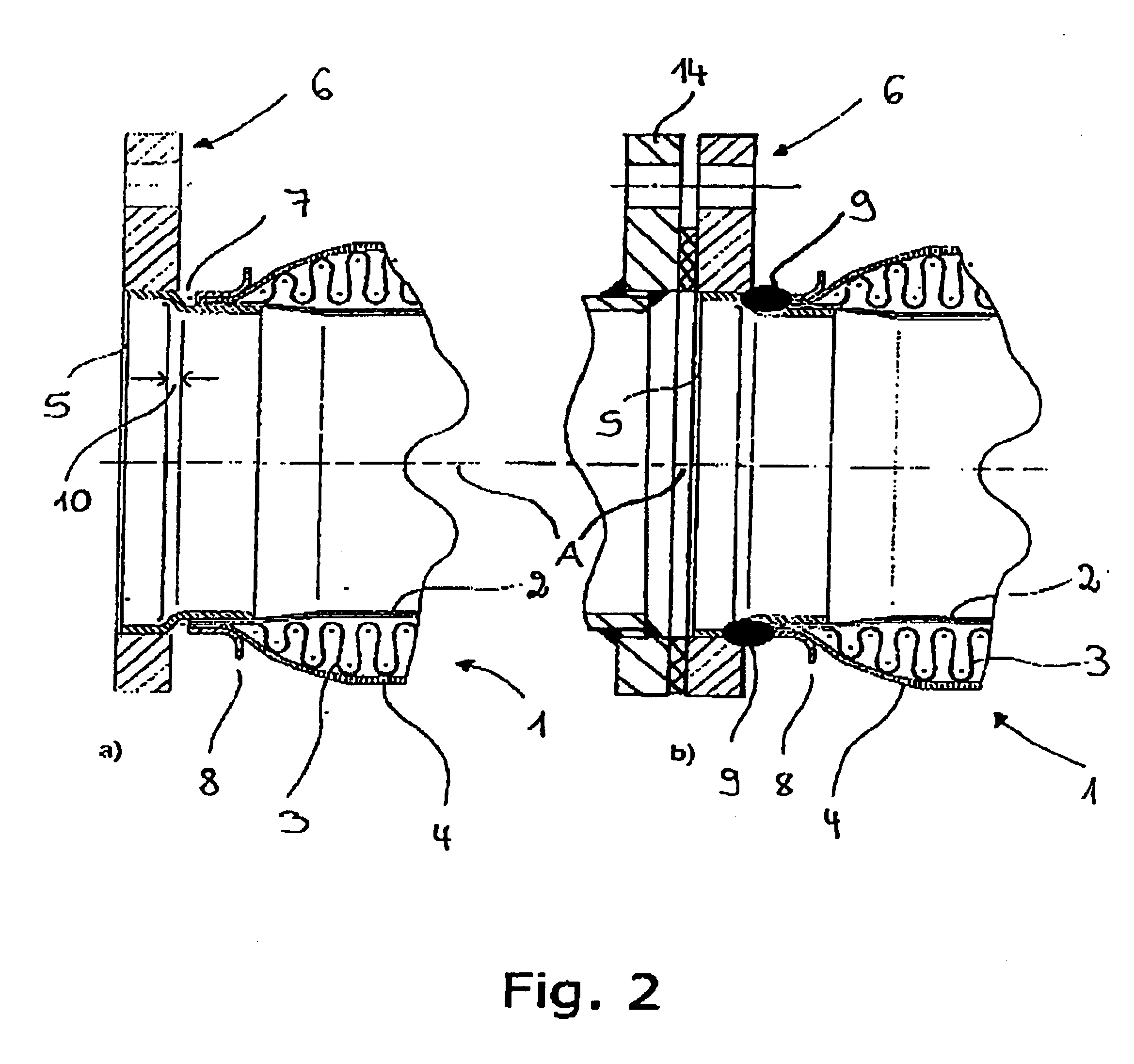
[0032]A short connecting tube 5, which, in the embodiment shown, is formed as hollow cylinder with circular cross-section is positively inserted with one end in a connecting flange 6 and with the other end in the metal tube 1 such that only a small gap 7 remains between the connecting flange 6 and the metal tube 1. An angle flange 8 is also disposed at the gap-side end of the metal tube 1.
[0033]FIG. 1b shows a weld seam 9 which joins together the connecting tube 6, along its entire periphery and in the region of the gap 7, with the connecting flange 6 and all layers 2, 3, 4, 8 of the metal tube 1. Towards this end, the weld ...
PUM
| Property | Measurement | Unit |
|---|---|---|
| Length | aaaaa | aaaaa |
| Thickness | aaaaa | aaaaa |
| Diameter | aaaaa | aaaaa |
Abstract
Description
Claims
Application Information
 - R&D
- Intellectual Property
- Life Sciences
- Materials
- Tech Scout
- Unparalleled Data Quality
- Higher Quality Content
- 60% Fewer Hallucinations
Browse by: Latest US Patents, China's latest patents, Technical Efficacy Thesaurus, Application Domain, Technology Topic, Popular Technical Reports.
© 2025 PatSnap. All rights reserved.Legal|Privacy policy|Modern Slavery Act Transparency Statement|Sitemap|About US| Contact US: help@patsnap.com


